In my Raspberry Pi starter kit I also got a LCD display based compatible with the Hitachi HD44780U controller.
WiringPi has some nice simple support for this.
The LCD supports being driven in 8 bit mode (which requires 10 GPIO pins) and 4 bit mode (which required 6 GPIO pins). Although you can use all 17 GPIO pins for your own purposes I want to keep the I2C, UART and SPI functionality free for further projects, which means I only really have 8 pins to play with. I also want to connect up my 1 wire temperature sensor and later on my infrared sensor. This means that even using the LCD in 4 bit mode I’m going to be running out of pins.
Fortunately the GPIO is quite extensible using the I2C or SPI pins. The simplest way to do this is to use the MCP23S17 which is supported by WiringPi.
The Pi has 4 pins supporting SPI:
- CEO, CE1 - chip select pins
- SCLCK - Clock
- MISO - Master in, slave out
- MOSI - Master out, slave in
Connecting the MCP23S17 is simply a case of connecting these pins up.
- PIN 11 (CS) -> CE0 (or CE1)
- PIN 12 (SCK) -> SCLCK
- PIN 14 (SO) -> MISO
- PIN 13 (SI) -> MOSO
- PIN 9 (VSS) -> 3v
- PIN 10 (VDD) -> GND
- PIN 15-17 (A0-A2) -> GND - This sets the address of our chip to ‘0’
- PINT 18 (_RESET) -> 3V - Don’t forget this like I did - you’ll be scratching your head for a while…
You can then connect whatever you want to pint 21-28 and 1-8.
Connecting up the LCD display should be straightforward. I was fortunate that the pins on my connector married up really nicely with the pins on the MCP23S17 as shown here:
A and K (Anode and Cathode) for the back-light are connected the VSS and VDD pins - I’m able to do that with my module because it has a built in resistor - you should check your module first!
The data pins for the LCD match up with pins 1-8 on the MCP23S17. I’m going to use the LCD in 4 bit mode so I can use a couple of these pins to drive the E and RS connections on the LCD.
If your LCD module is 5v, make sure you tie the RW pin to ground.
VSS is connected to 5v and VDD is connected to GND.
V0 controls the contrast - initially I had this wired up to a 10K pot, but once I’d found a good setting I replaced that with two resistors dividing +5 and GND.
That’s it for the wiring up. To make it do something we have to install wiringPi and write some simple code.
#include <stdio.h>
#include <wiringPi.h>
#include <mcp23s17.h>
#include <lcd.h>
#define BASE 100
int main (void)
{
wiringPiSetup () ;
mcp23s17Setup (BASE, 0, 0) ;
int fd = lcdInit(2, 16, 4, BASE + 10, BASE + 11, BASE + 12, BASE + 13, BASE + 14, BASE + 15, 0, 0, 0, 0);
lcdHome (fd);
lcdClear (fd);
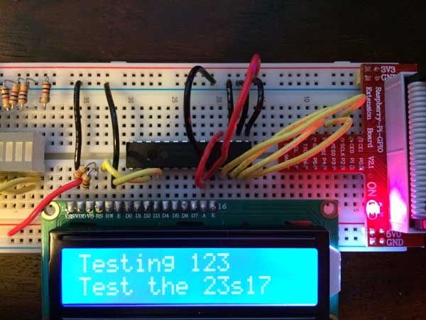
lcdPuts(fd, "Testing 123");
lcdPosition(fd, 0, 1);
lcdPuts(fd, "Test the 23s17");
}
The first step is to initialise wiringPi. We then need to initialise the SPI mcp23s17 as shown here. The first number (BASE) is our pin offset, the second number is the SPI port (0 or 1) and the third number is the address/device id.
For the LCD we we give the number of rows, columns and bits (4 or 8) and then list the pins as detailed here.
To compile and run this program you have to link with wiringPi and wiringPiDev and before running you have to load up the spi driver module.
g++ spi.c -L/usr/local/lib -lwiringPi -lwiringPiDev
gpio load spi
sudo ./a.out
With the 3 address lines and two chip selects you could potentially connect up 16 extenders to your Pi giving you 256 IO pins!