We’ve been looking at making PCB motors. So far, we’ve got some promising results, we can make a magnet jump around - and we can even make our motor turn. We can even get our motor up to pretty high speeds - 2700+ RPM - which is pretty bonkers. You can watch a video version of this post here - there are a lot of nice animations in it:
One of the questions that have come up a few times is why people building these PCB motors tend to use wedge-shaped coils instead of round coils. It’s a pretty interesting question - let’s try and get to the bottom of it.
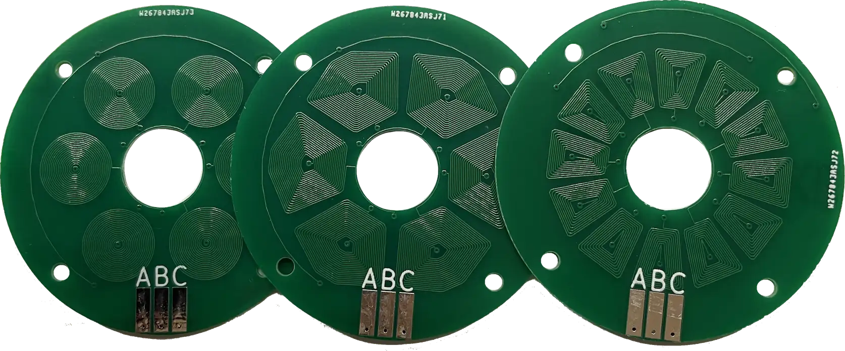
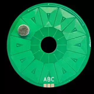
There is a somewhat intuitive answer to the question, which is simply that you can fit a lot more copper on the board if you use a wedge shape instead of a coil - this is particularly true as you try and fit more coils around the circle.
That’s the intuitive explanation, but let’s try and be a bit more scientific.
First off, let’s think about what we are trying to achieve. We want to generate a magnetic field that will create a force on a magnet to turn our rotor. This means that what we need is a force in the direction shown in this diagram.
The first way to approach this analysis is to try and simulate the fields that are being generated by our coils. Googling around on how to do this took me to something called the Biot Savart Law - this in turn led me to some nice Python code that will compute the magnetic field generated by an arbitrarily shaped coil.
All you need to do is feed in the points of your coil along with a value for the current flowing through it and you’ll get a 3D space containing your magnetic field.
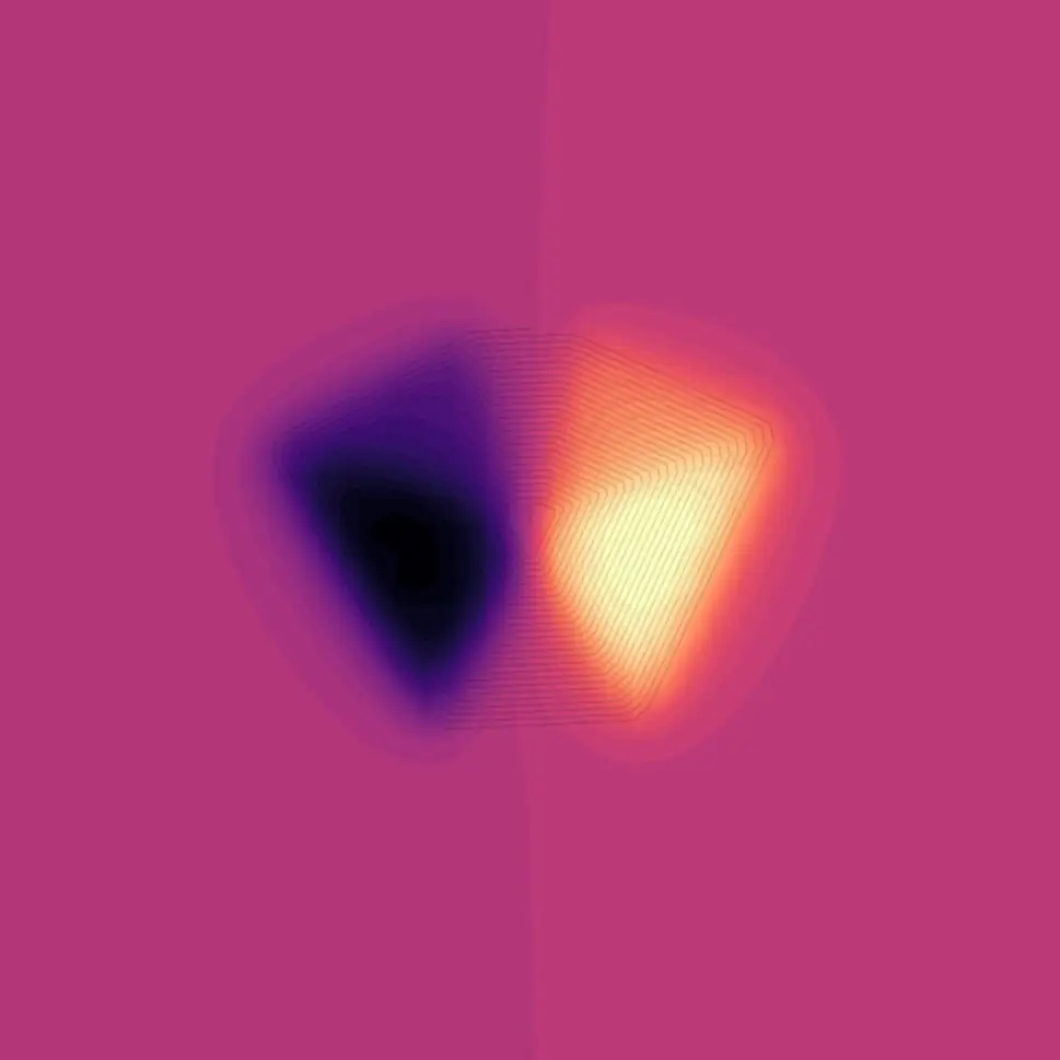
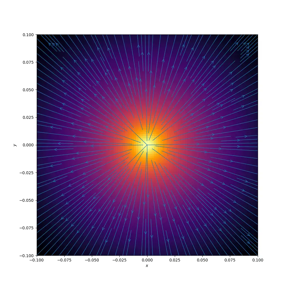
If we simulate our simple spiral coil we can examine the magnetic field just above the coil. As you’d expect we have a very strong Z component pointing out from the coil giving us a north pole.

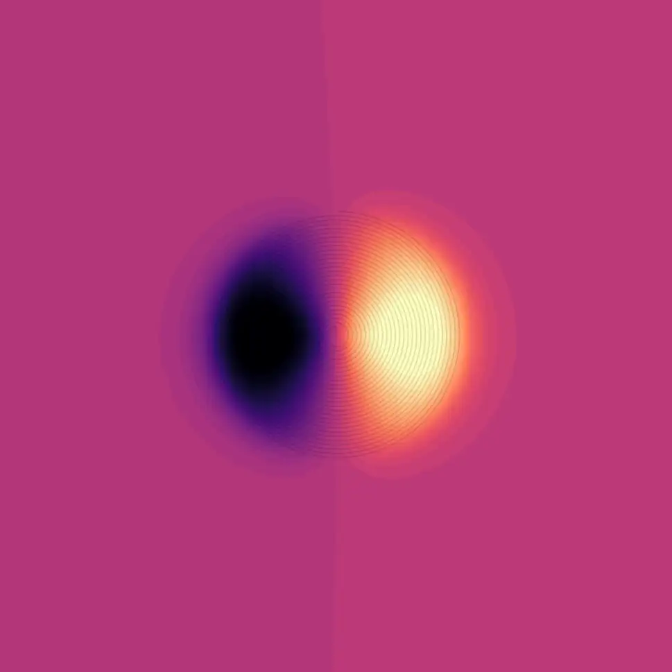
Looking at the X component of the field we can see that our field is pointing out to the left and right of the coil
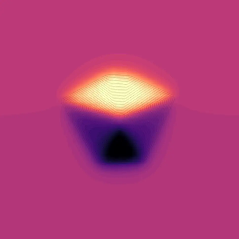
And similarly, for the Y component, it’s pointing up and down.
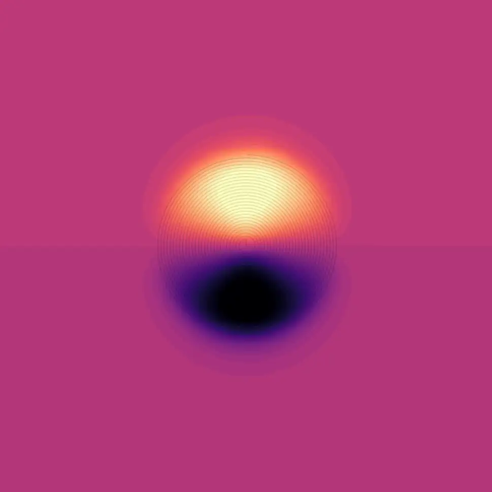
This makes much more sense if we look side-on at the coil and take a cross-section through the centre of the coil.
It’s a pretty interesting simulation. We can do the same for our wedge-shaped coil. Here we can see the Z component, so we can see that once again we are getting a strong magnetic field in the Z direction
the X component of the field is again pointing left and right
and the Y component is pointing up and down.
Again taking a slice through the middle of the coil we can see something that looks pretty sensible.
What’s pretty clear from both our coils is that we can easily generate a strong magnetic field in the Z direction. This will either attract or repel the pole of a magnet - the problem is that this strong field is not going to help turn our motor. If anything it may make it more difficult as our bearing is going to be put under load as the magnets are either pulled or pushed towards the coil.
The only field directions that we’re really interested in are the ones that will generate torque on our system and rotate our motor. These will be the components of the fields in the X direction pointing left and right.
If we ignore the Z and Y components of the field and sum up the negative and positive X component values we can do a very simple comparison of our coil shapes.
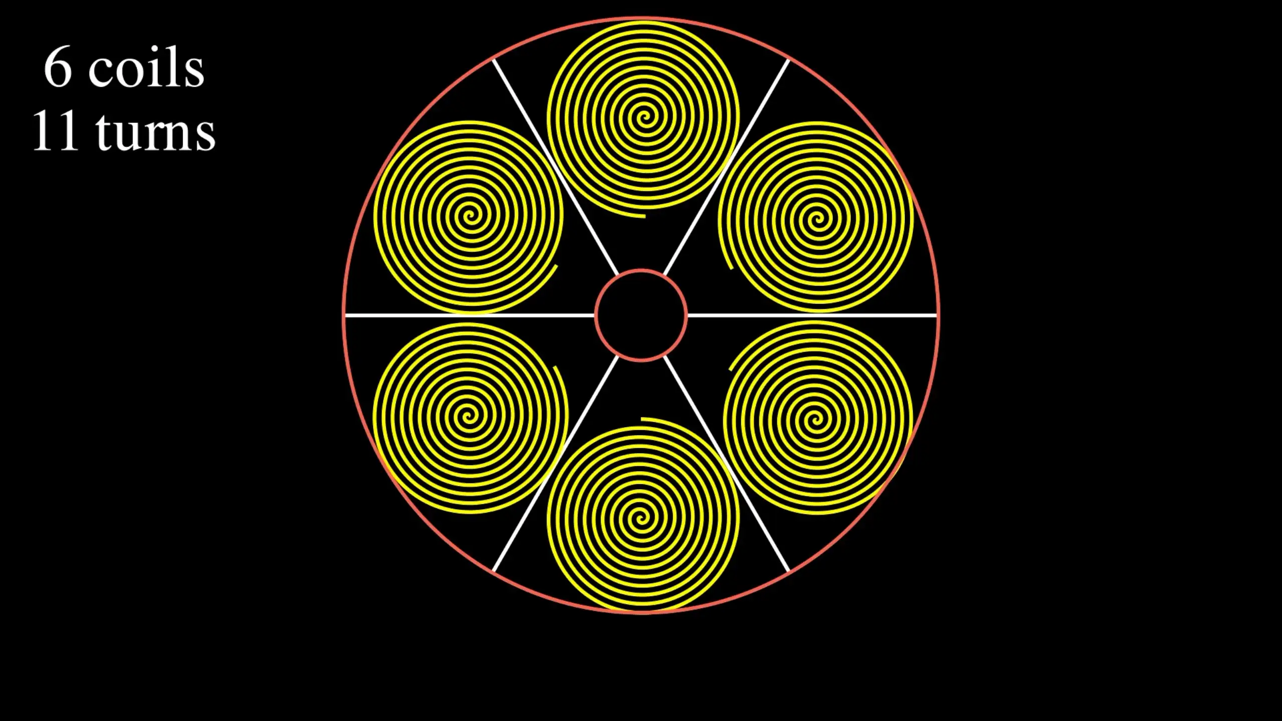
With the 6-coil version, there isn’t a huge amount of difference. This kind of makes sense as we can have quite large circular coils, so we’re not getting that much benefit from our wedge shape.
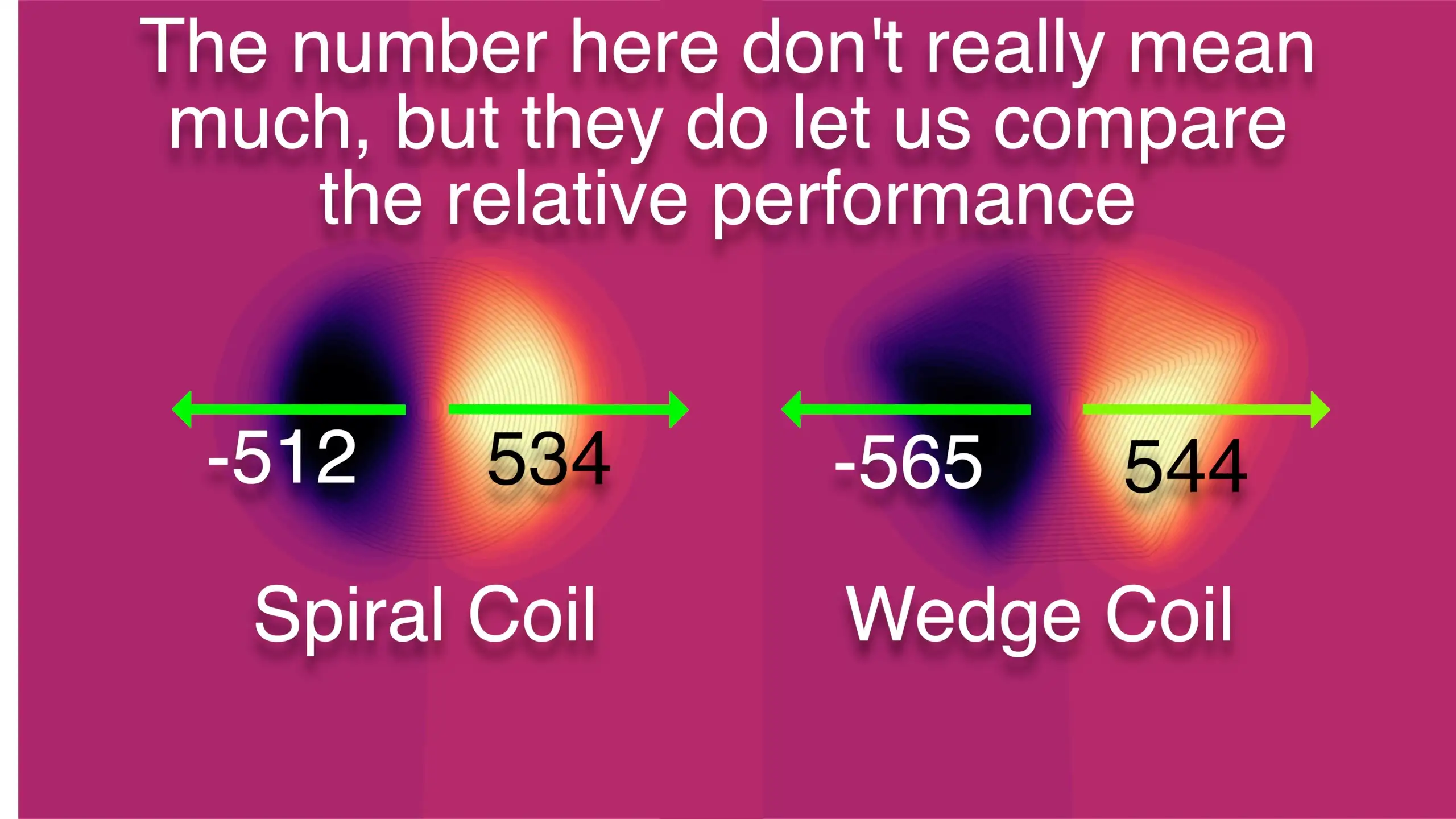
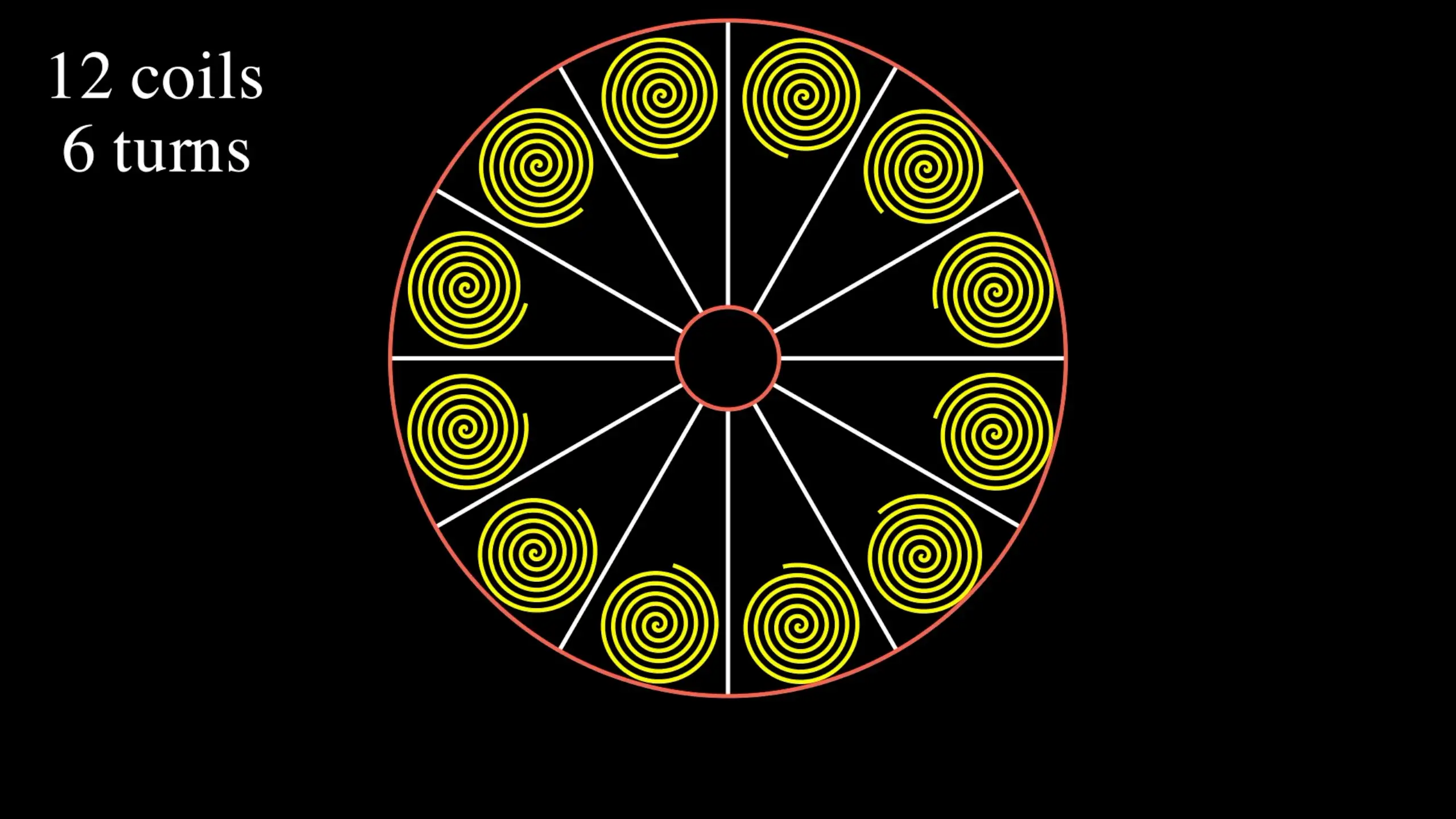
However, if we move to the 12 coil versions there’s quite a dramatic difference. We’re able to fit a lot of radial long wires in, which gives us a really nice field in the X direction.
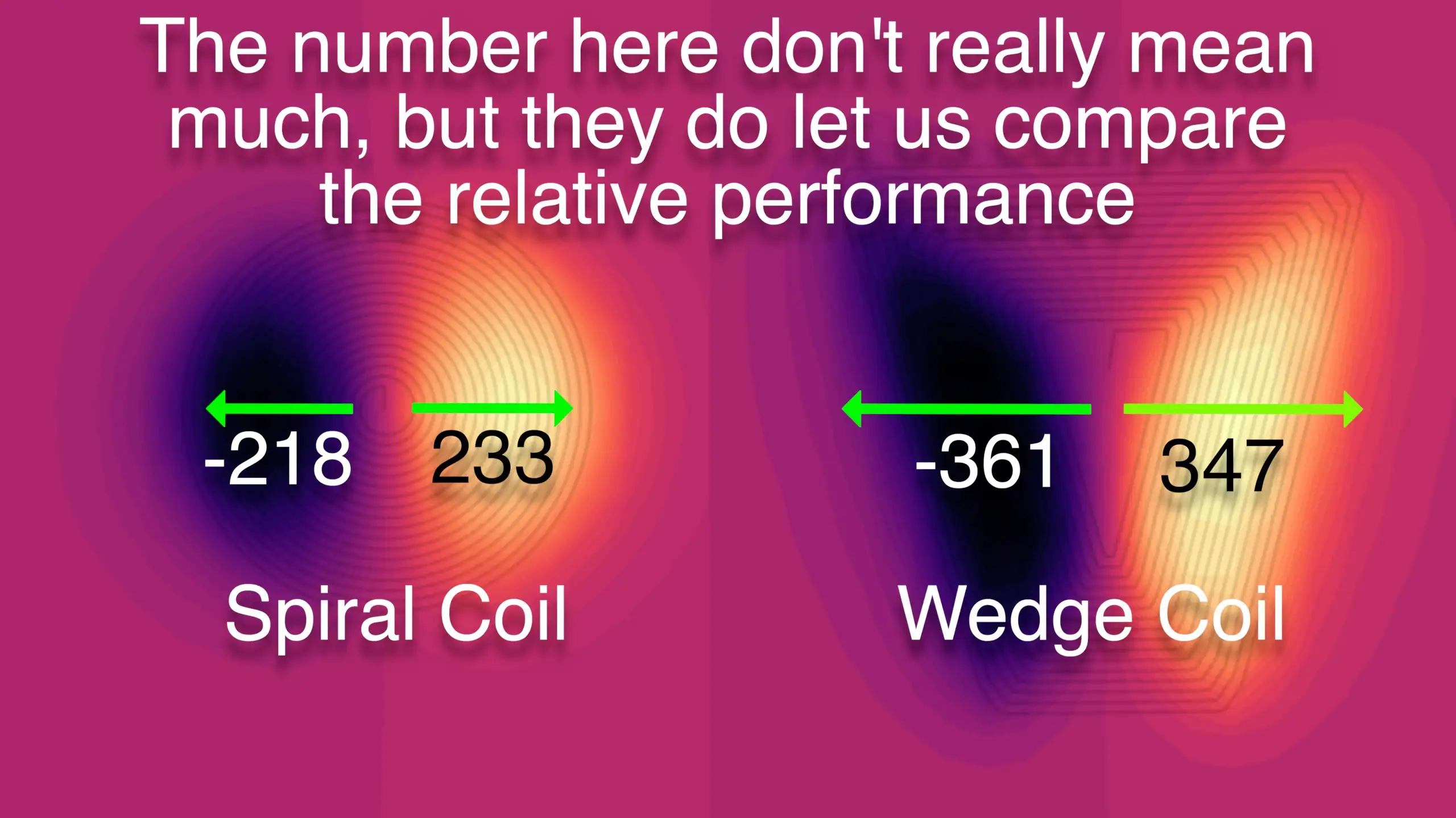
So looking at the magnetic fields the coils are generating we have a pretty clear win for the wedge coils - particularly for the 12-coil version.
Alternatively, we can approach this problem from the opposite direction, given a magnet, what force will be exerted on our coil?
To calculate this we need to know the magnetic field strength and direction being generated by our magnet. Knowing this, we can simulate the force that would be applied to our coil for a given current.
So our first challenge is to simulate the magnetic field from one of our magnets.
The simplest approach to this would be to model our magnet as a simple dipole.

The formula for the magnetic field for a dipole is this. This looks a little complicated, to begin with, but it’s actually pretty simple.
\[B(\boldsymbol{r}) = \frac{\mu_0}{4\pi} \left[\frac{3r(\boldsymbol{m}.\boldsymbol{r})}{r^5} - \frac{\boldsymbol{m}}{r^3} \right]\]The bold r is the vector from the magnet to a point in space, the bold m is the magnetic moment of our magnet, and r is the distance from our magnet. Splitting this formula into the X, Y and Z components and making the magnetic moment point in the Z direction we end up with these three very simple equations.
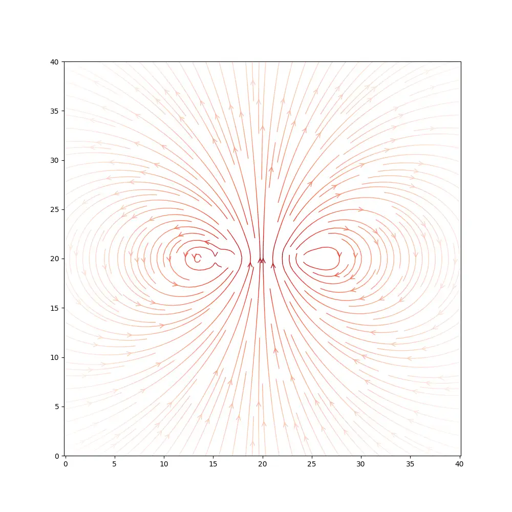
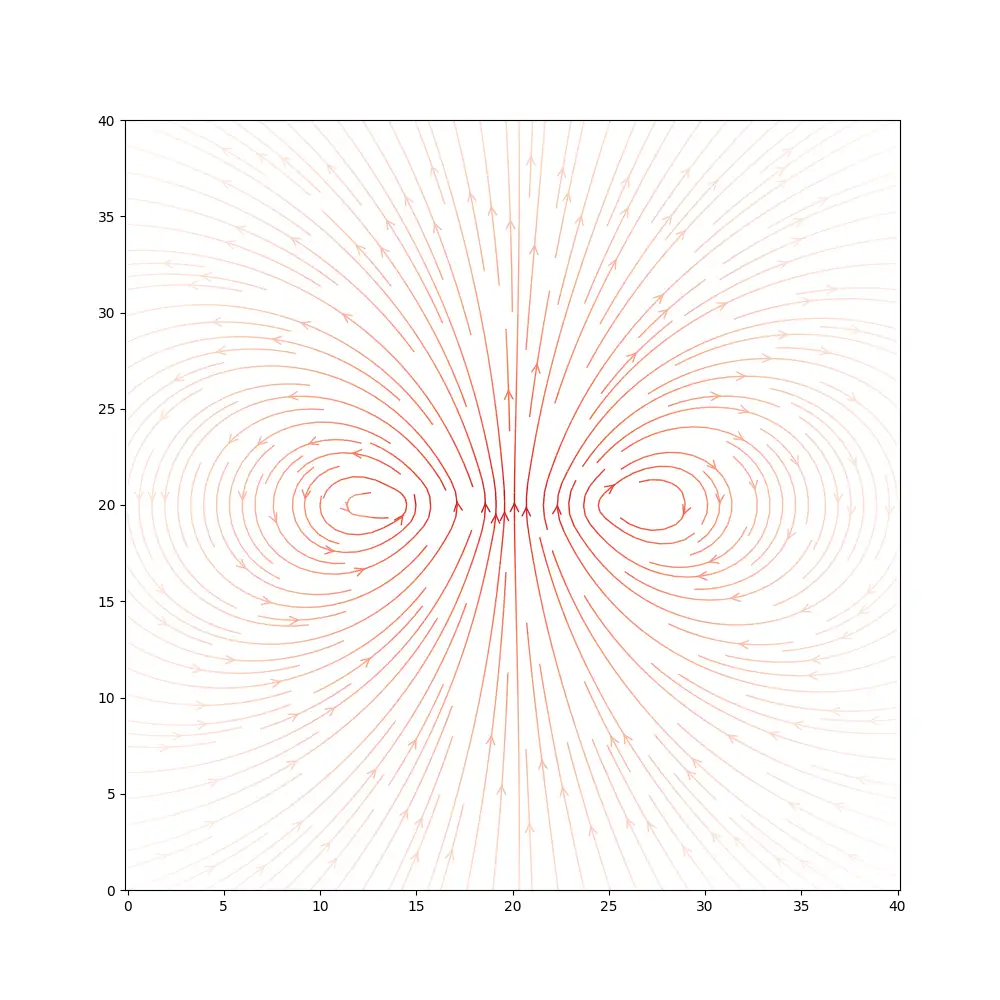
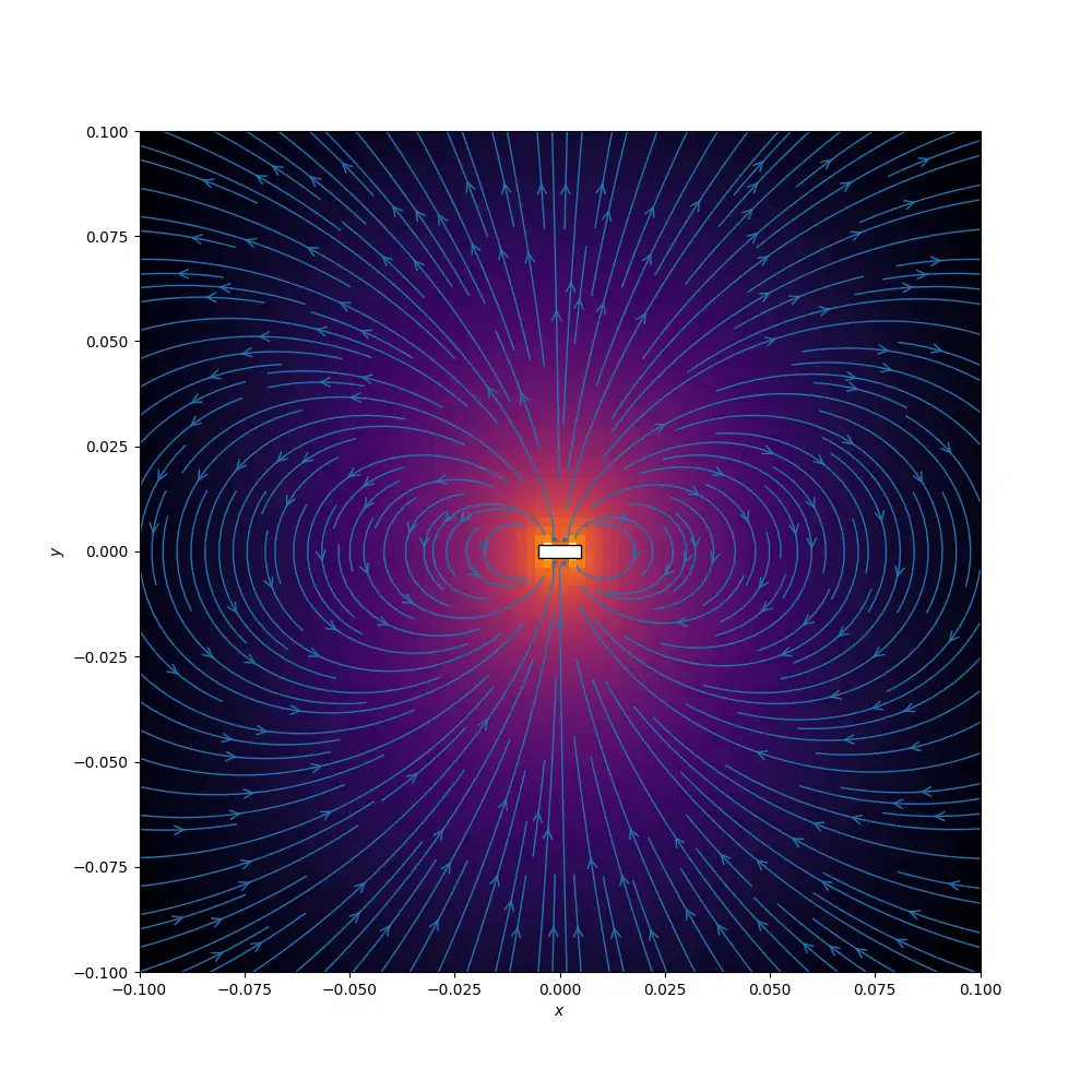
\[B_x = \frac{\mu_0}{4\pi} \left[\frac{3r_x m_z r_z}{r^5}\right]\] \[B_y = \frac{\mu_0}{4\pi} \left[\frac{3r_y m_z r_z}{r^5} \right]\] \[B_z = \frac{\mu_0}{4\pi} \left[\frac{3r_z^2 m_z}{r^5} - \frac{m_z}{r^3} \right]\]Using these equations we can calculate the magnetic field at any point in 3D space. Here’s a slice of the field looking side-on at the magnet. It looks exactly as you’d expect from your high school physics experiments.

And here’s a slice of the field looking up at the magnet from below.
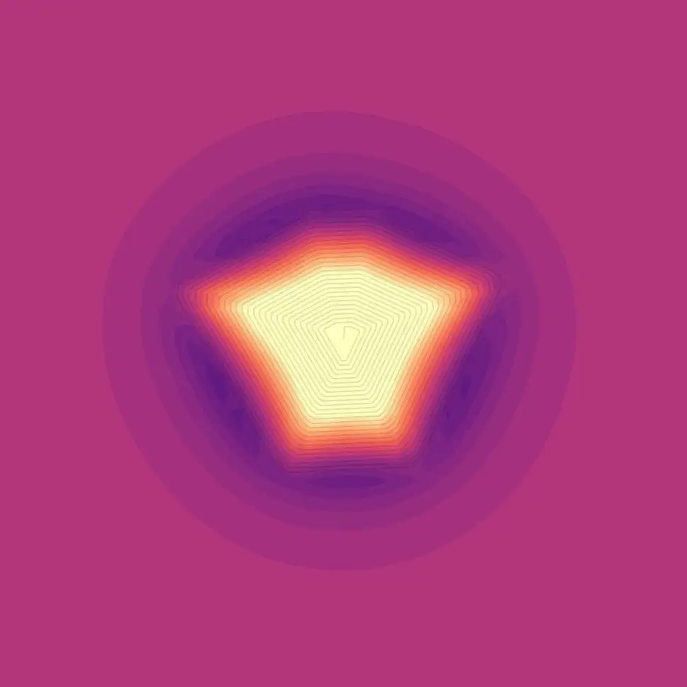
We can approximate the field from one of our disk magnets by combining multiple dipole magnets. Here’s a simulation where I’ve used 6 dipole magnets around the edge of our disk magnet.
We could probably get away with just using the simple dipole for our simulations, but it’s interesting to try and make it a bit more accurate.
To work out the total force acting on our coil from the magnetic flux we chop the coil into small segments and calculate the force on each individual segment. We can sum up all these small forces to get the total force acting on the coil.
\[\vec{F}_l = \vec{I} l \times \vec{B}\]Where F is the force, I is the current, l is the length of the segment, and B is the magnetic field strength at the segment.
\[\vec{F}_{total} = \sum{\vec{F_l}}\]We’re trying to work out how well this force will rotate the system, so I thought it would be interesting to simulate the forces generated as a magnet sweeps around the stator.
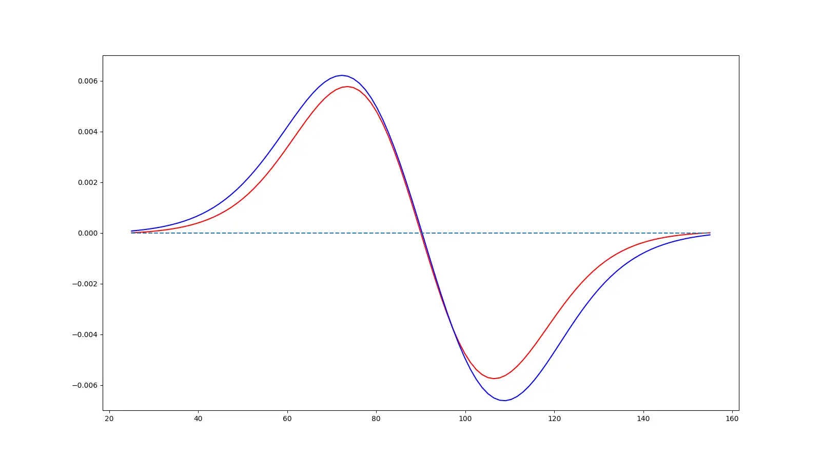
Here’s the result for the spiral coil from the 6-coil PCB, and the result from the wedge coil. As we’d expect from our previous simulations of the coil magnetic fields, we don’t see that much difference.
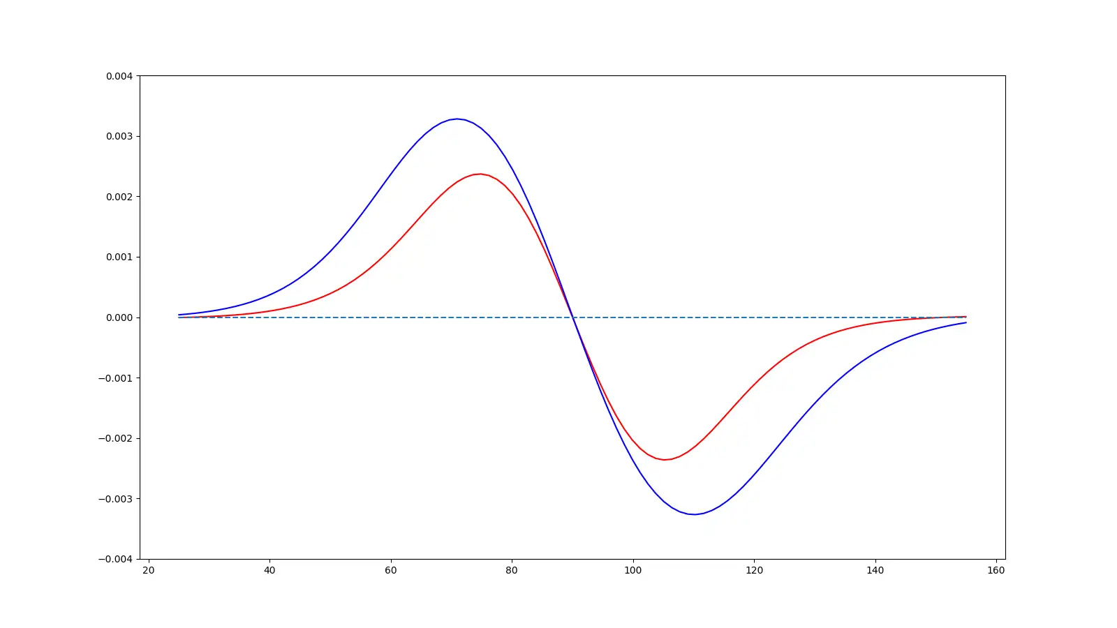
But, if we do the same with the 12 coil PCBs we can see quite a dramatic difference. We’re getting a lot more force applied from our wedge shaped coil compared to the spiral coil.
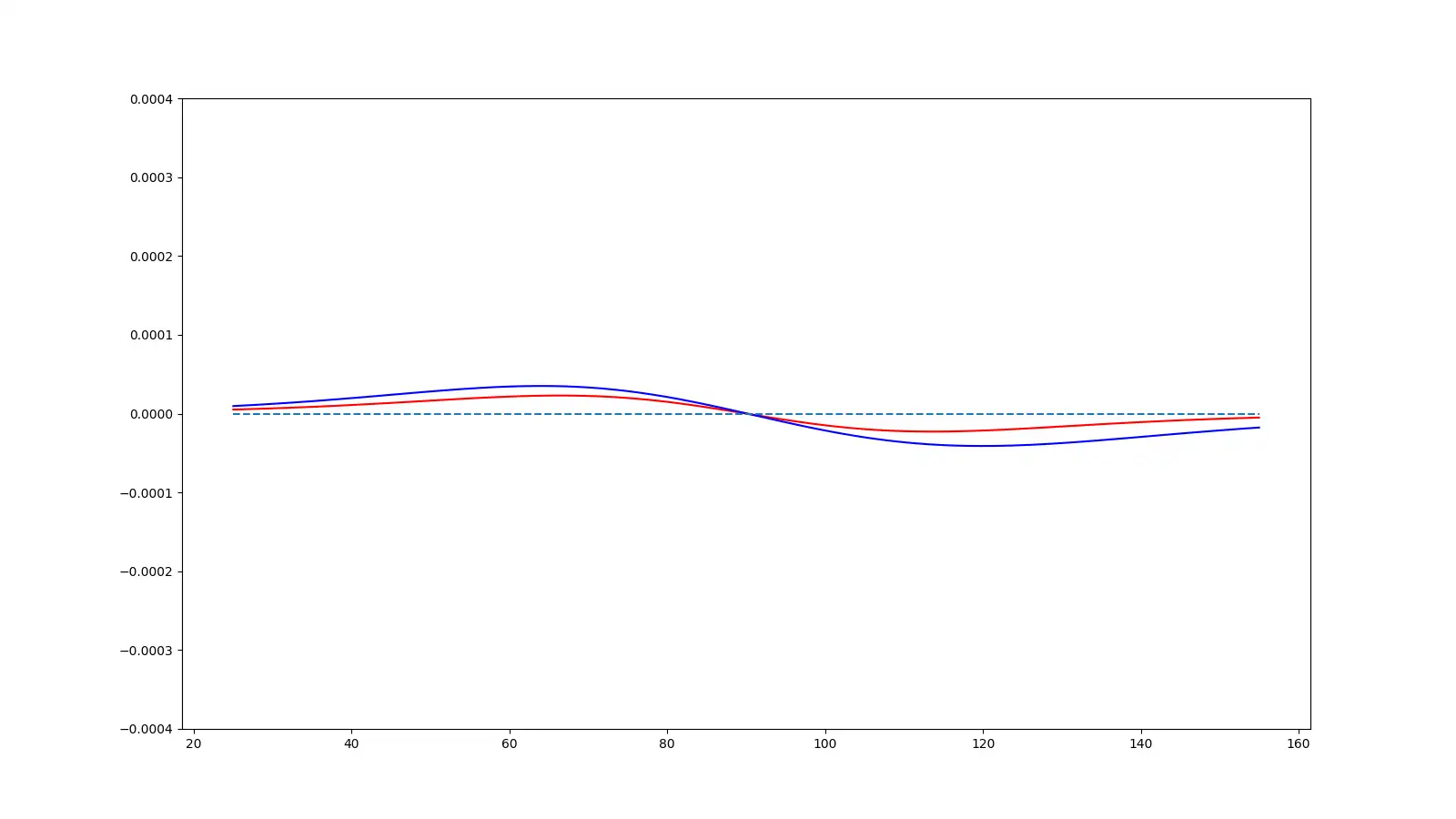
One very interesting thing is just how quickly these forces disappear as we move the magnet away from the coils in the Z direction - this tells us that we need to keep our magnets very close to the surface of the PCB if we want to get a good amount of force.
So, hopefully, this answers the question of why people go with wedge-shaped coils, you can simply fit more radial lines in and the radial lines are the most important parts of the coils as they generate the fields in the correct direction to create torque.
There are other ways of winding the coils - but they are quite a bit more complicated - further research is required!