I’ve been messing around making PCB coils, but instead of drawing them by hand, which would be pretty frustrating, I’ve automated the entire process.
You can watch a video version of this blog post here (it’s worth it as there are a lot more animations!):
I’m working on a new project with one of my friends and we’ve taken inspiration from Carl Bugeja’s amazing work on PCB Motors. If you haven’t seen his channel then check it out it’s very very cool.
Now it’s not clear if what we’re doing will actually work as well as his projects, but there’s only one way to find out and that’s to get some boards made up.
For our PCB coils, we want to create as many turns as possible.
Our main constraint is going to be our track width and track spacing along with the number of layers that we can use.
Looking at PCBWay we can see that prices start to go up very quickly as soon as we go below 5mil for the track width and spacing.
So this will be the smallest size we’ll try and use. This is equivalent to a track width and spacing of 0.127 millimetres each.
Staying on the theme of keeping it cheap, we’ll also be using a two-layer board. Going up to a four-layer board would increase the cost considerably.
These constraints may make our coils too weak to do anything, but we’ll see once we’ve done some more experiments - as you can see from the video above, we’ve already made some progress.
To make a simple coil, all we need to do is generate a spiral.
If we were just trying to make a circular track, then we would follow the equations here and sweep the angle from 0 to 360 degrees.
We would then generate points on the circle by sweeping the angle from 0 to 360 degrees and keeping the radius constant.
To make a spiral we just need to make the radius increase proportionally to the current Angle.
Now we can calculate the coordinates on a spiral by sweeping our angle from 0 to 360 Degrees multiplied by the number of turns that we need.
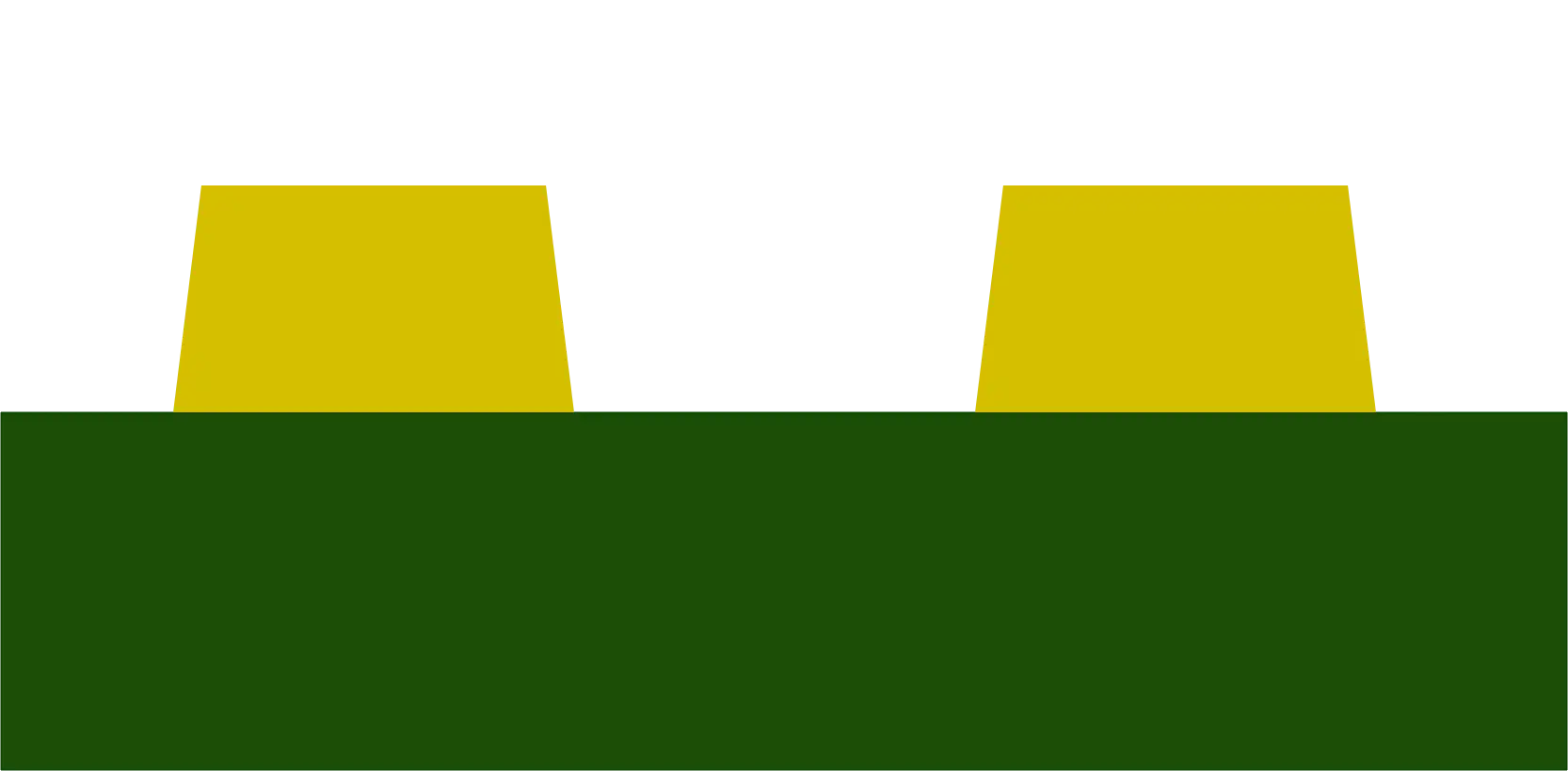
We’re going to also want to have a coil on the bottom layer of the board.
So we’re going to need some space in the centre for a via to connect the top and bottom layers.
We can do this by starting our radius off with a small offset. We can now just join our top and bottom chords together using a via in the centre.
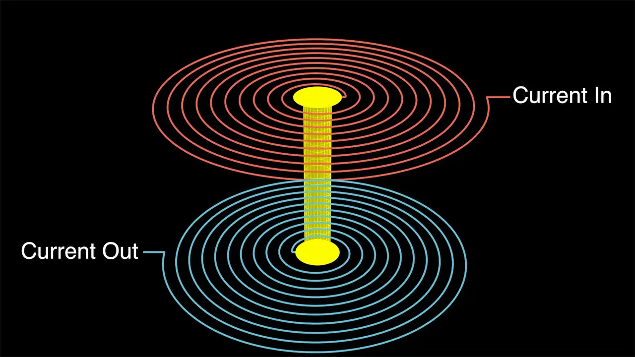
If we look at the direction of the magnetic field that will be created from the two coils we can see that they will cancel each other out.
To fix this we just need to flip the bottom coil.
The current will now flow into the top coil and out of the bottom coil in the same direction.
The top and bottom coils will now reinforce each other.
Now we’re going to be trying to repeat some of Carl’s work and make a three-phase PCB motor.
For this kind of motor, we’re going to need three coils spaced 120 degrees around our PCB.
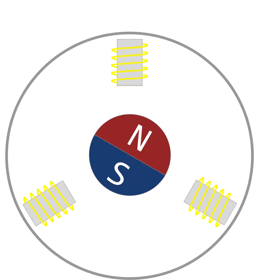
The motor can be made more powerful by duplicating each coil on the opposite side of the PCB. So we end up with six coils in total.
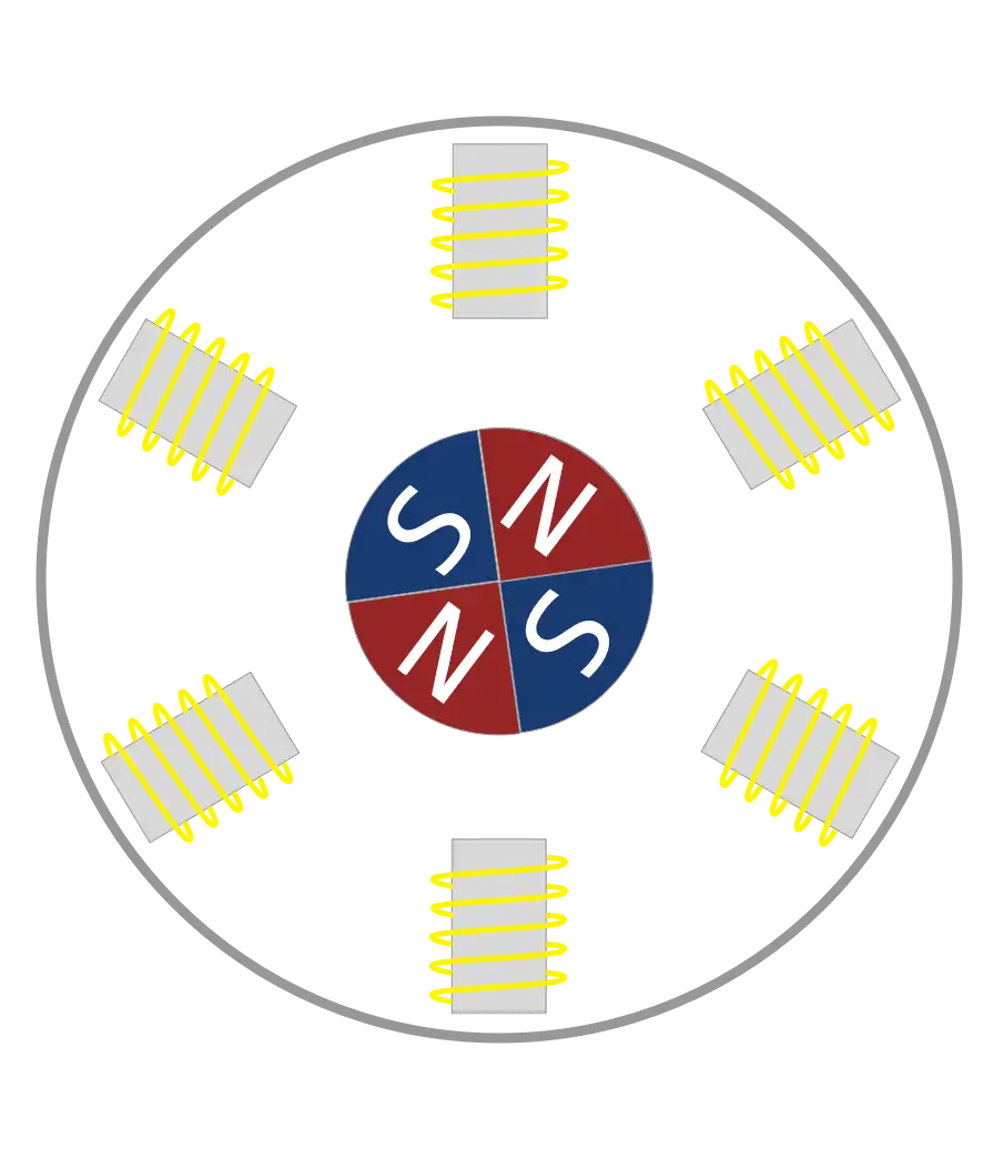
To make the wiring up of these coils easier I’m adding a 180-degree offset to the angle on the bottom coil so that the end of the coil finishes on the opposite side to the start of the coil on the top layer.
We can now easily connect the pairs of coils together by connecting the ends of the coils on the bottom layer.
To make the current flow in the correct direction we just need to flip the Y coordinates of the opposite coils again.
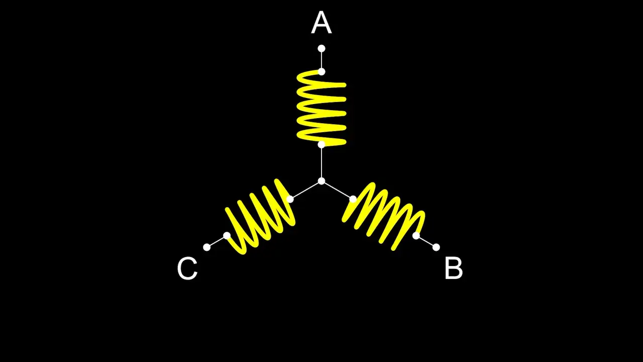
Connecting the ends of the opposite coils together to a common Point gives us the classic star wiring pattern.
So this is great, but if we look at some images of other people’s PCB stators we can see that they don’t always stick to circular coils.
How about generating arbitrarily shaped coils?
This turned out to be a surprisingly interesting problem.
My initial attempts produce some very interesting shapes. I tried to take the existing code for creating spirals but calculated the radius by sweeping an angle around and casting a ray out to find the intersection point with the template shape.
I used the distance from the origin to this intersection point as the radius and then tried offsetting this.
Now obviously, this doesn’t work very well. And if we think about what is happening with a normal spiral we can intuitively see that we are always offsetting points at approximately a normal to the template circle shape.
So, what we need to do is offset the intersection point at right angles to the line it belongs to.
If we do this then we get something that looks much better the only issue is that it doesn’t seem to handle corners - they are getting chopped off.
My first attempt to solve this was simply to smooth the corners of the template shape.
There’s a really nice algorithm we can use to do this automatically called Chaikin’s corner-cutting algorithm.
This iteratively smooths lines and gives a really nice smooth result after just a couple of iterations.
If we do this first and then run our algorithm we get quite reasonable results.
However, we’re not really ending up with the shape that we originally wanted.
An alternative way to fix the corner cutter problem is to detect when we switch to a new line segment and create an intermediate point where the corner should be.
We do this by calculating the intersection of the previously generated points with the next two generated points.
This algorithm works really well and we get a nice-looking coil.
The only issue we face now is that we can miss small details in our template shape.
We are sweeping a ray around a circle and unless we step with very small increments we can easily miss a line segment.
But, if we step with really small increments then it takes a very long time to process.
So, what I’ve ended up doing is taking each point on the template. I calculate the angle from the point to the origin and from that, I can then work out how much offset would be required.
This generates pretty much the same results as our original sweeping ray algorithm with the additional points, but it’s a lot faster and it doesn’t miss any line segments.
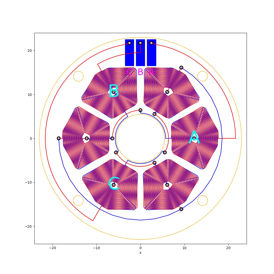
This works really well and we can create pretty cool wedge-shaped coils.
Here’s the version with six coils:
and we can even generate 12 coils instead. The wiring up is a bit more complicated but it can still all be done programmatically.
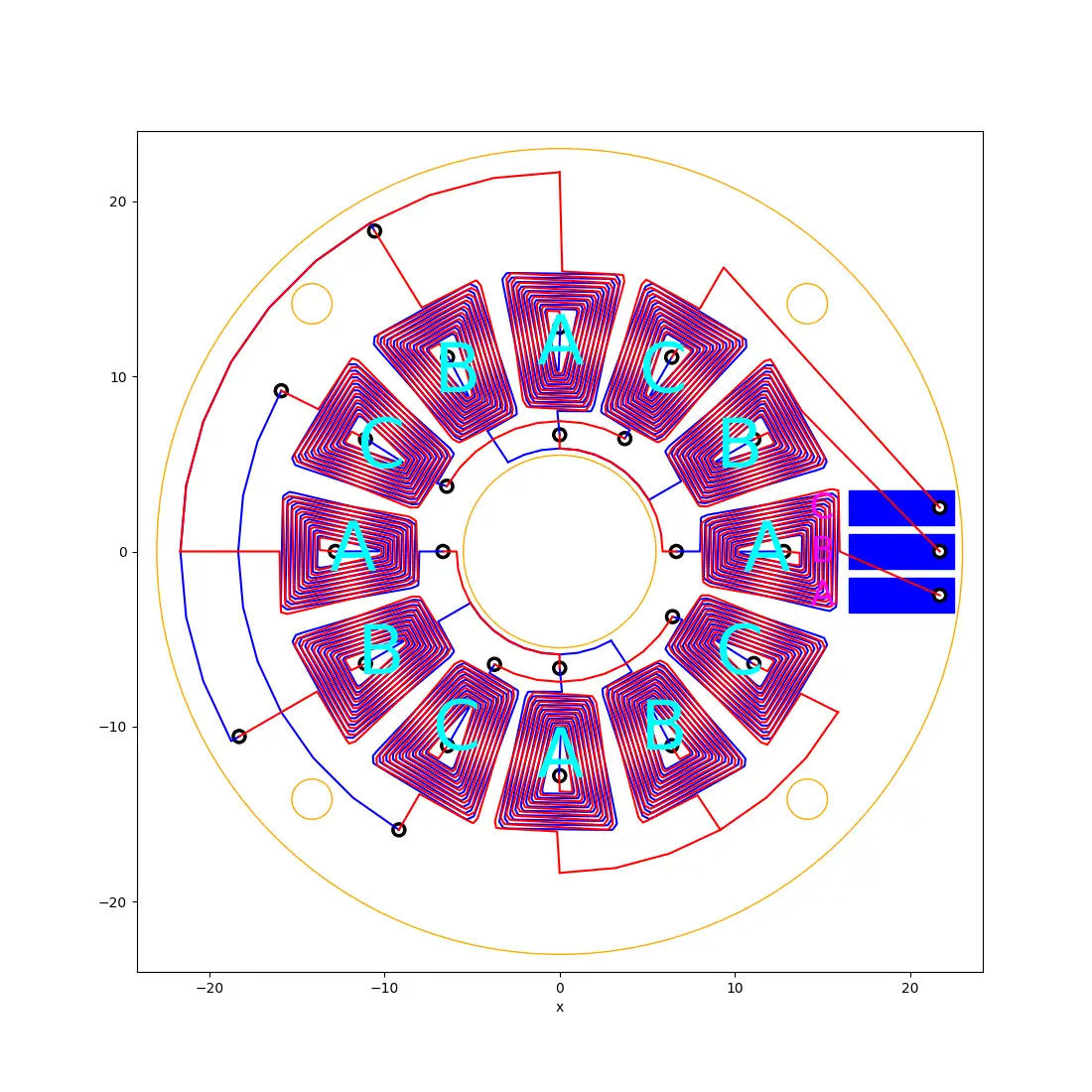
The 12-coil version still creates the same star-shaped circuit as the six-coil version.
Everything is fully automated using a KiCad plugin.
Making a keycard plugin was an adventure in itself. In many ways, it was almost as hard as actually getting the coil algorithm.
There are a couple of issues with making KiCad plugins - they are pretty hard to develop and test - you need to edit your code, refresh the plugins, run the plugin, and see if it works.
It’s a slow process.
It’s also quite hard to include additional Python libraries that your plugin might rely on.
KiCad comes with its own installation of Python. In theory, you can add new python libraries using the bundled pip installer.
However, on modern Mac computers, this causes all sorts of problems.
Macs have an additional security layer that prevents applications from being modified. This does help prevent viruses and malware from infecting your computer, but unfortunately running pip install in the KiCad directory modifies the KiCad python installation.
So the operating system thinks it’s no longer valid and won’t let you run it.
To avoid all these issues I’ve developed all the complicated code in a Python notebook. This lets me develop the coil generation algorithms much more quickly and I can easily preview what it will look like by plotting the output directly in the notebook.
The notebook produces a very simple JSON representation of the tracks, the vias, silk and pads. And my KiCad plugin simply reads this and creates the required objects.
It’s a really nice decoupling and it means we aren’t really tied to KiCad at all.
We could use any PCB layout tool that supports scripting that can read JSON data.
The KiCad python API is pretty difficult to get started with. The documentation is auto-generated from header files, so it doesn’t really tell you how to use it.
there are quite a few examples, but the API is pretty unstable and seems to change fairly often.
You often have to spelunk into the C++ code to see how things actually work.
A great example of this was just trying to work out how to draw a circle.
I could not work out how to set the radius - there’s no setRadius function!
Digging into the code it transpires that you use the distance between the start and end points to set the radius.
This is one of the big issues with auto-generating documentation from header files - there’s no context to help you understand how to use the API.
Having said that, it’s an open-source and free project. So I’m not going to complain too much. If I really wanted to make it better I should contribute some documentation back to the project.
I’ve put my code up on GitHub - https://github.com/atomic14/kicad-coil-plugins, hopefully, it will help other people.
You can watch all the animation (and a lot more in the video below):