View All Posts
read
Want to keep up to date with the latest posts and videos? Subscribe to the newsletter
HELP SUPPORT MY WORK: If you're feeling flush then please stop by Patreon Or you can make a one off donation via ko-fi
#DOOM #EFFICIENCY #PCBS #RASPBERRY PI #VOLTAGE INPUT #WIRELESS CHARGING #WIRELESS PI DOOM MACHINE

Ever since discovering these crazy wireless LEDs I’ve been messing around with wireless charging technology. So far I’ve been a bit disappointed with what I’ve been able to do, it’s been great for making LEDs light up, but my attempts to use it for anything serious have either resulted in me burning out the transmitters, or releasing the magic smoke from the circuit I’m trying to power.

LEDs

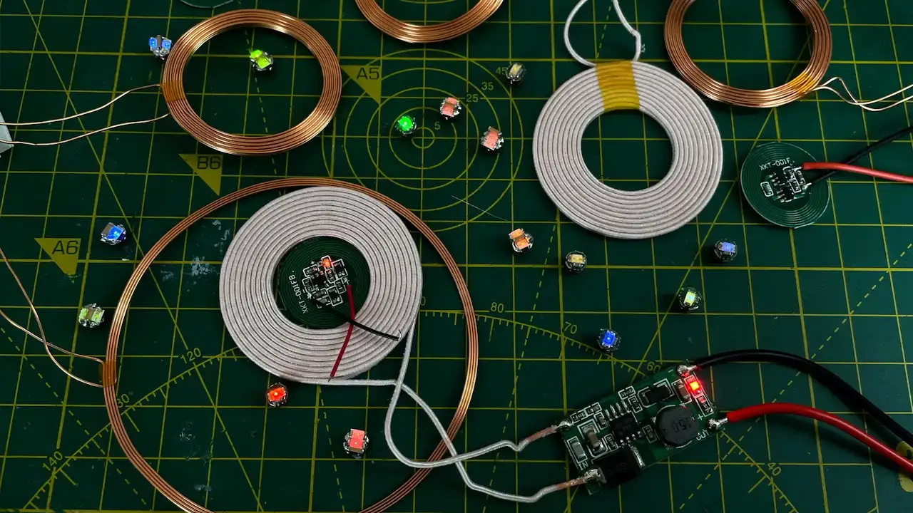
So I decided to bite the bullet and get a proper set of wireless charging PCBs. If you want to watch a full video of the experiments in this blog post then you can do so here - it’s definitely worth it!

Wireless Charging PCBs

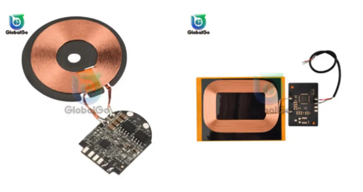
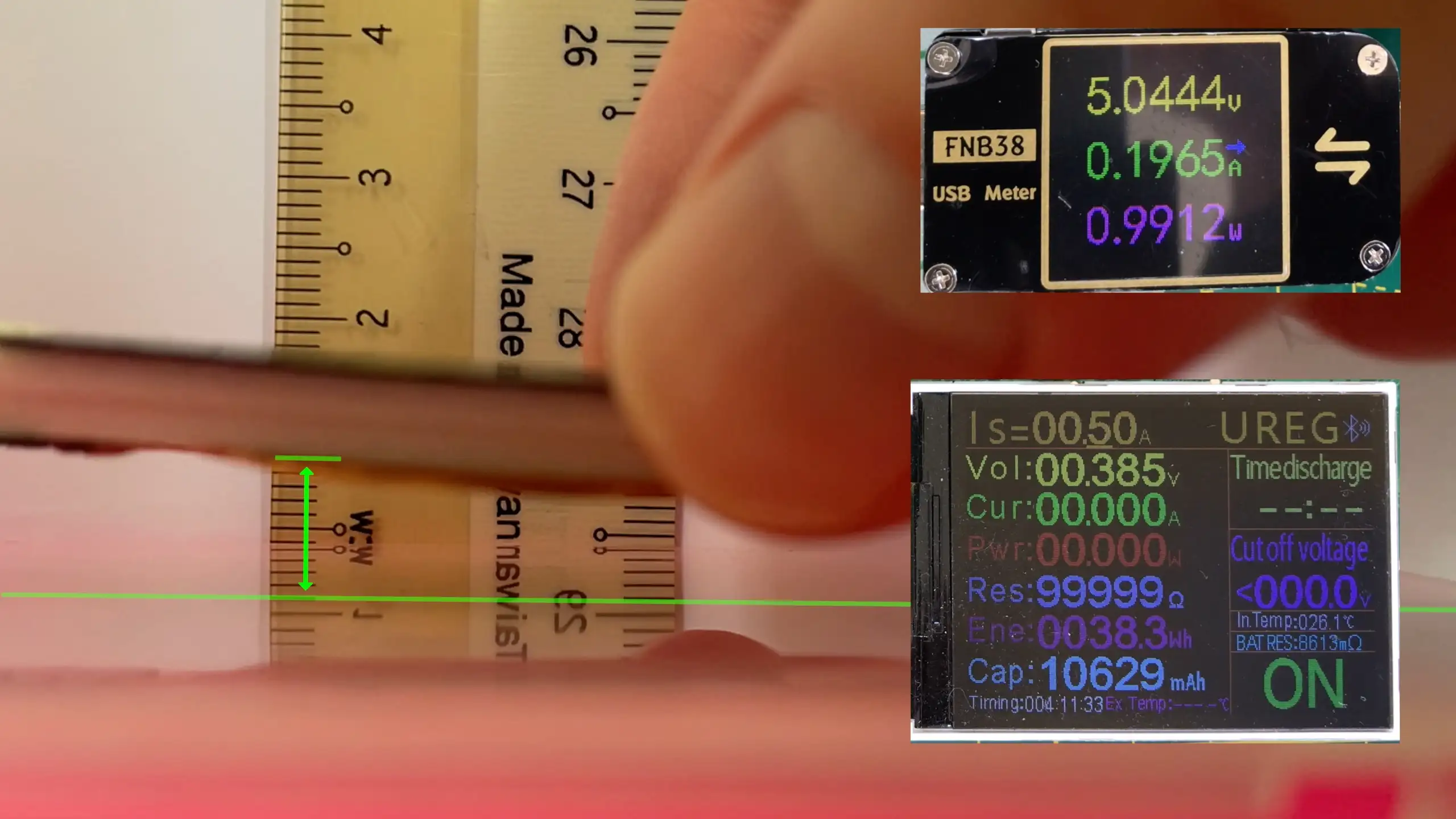
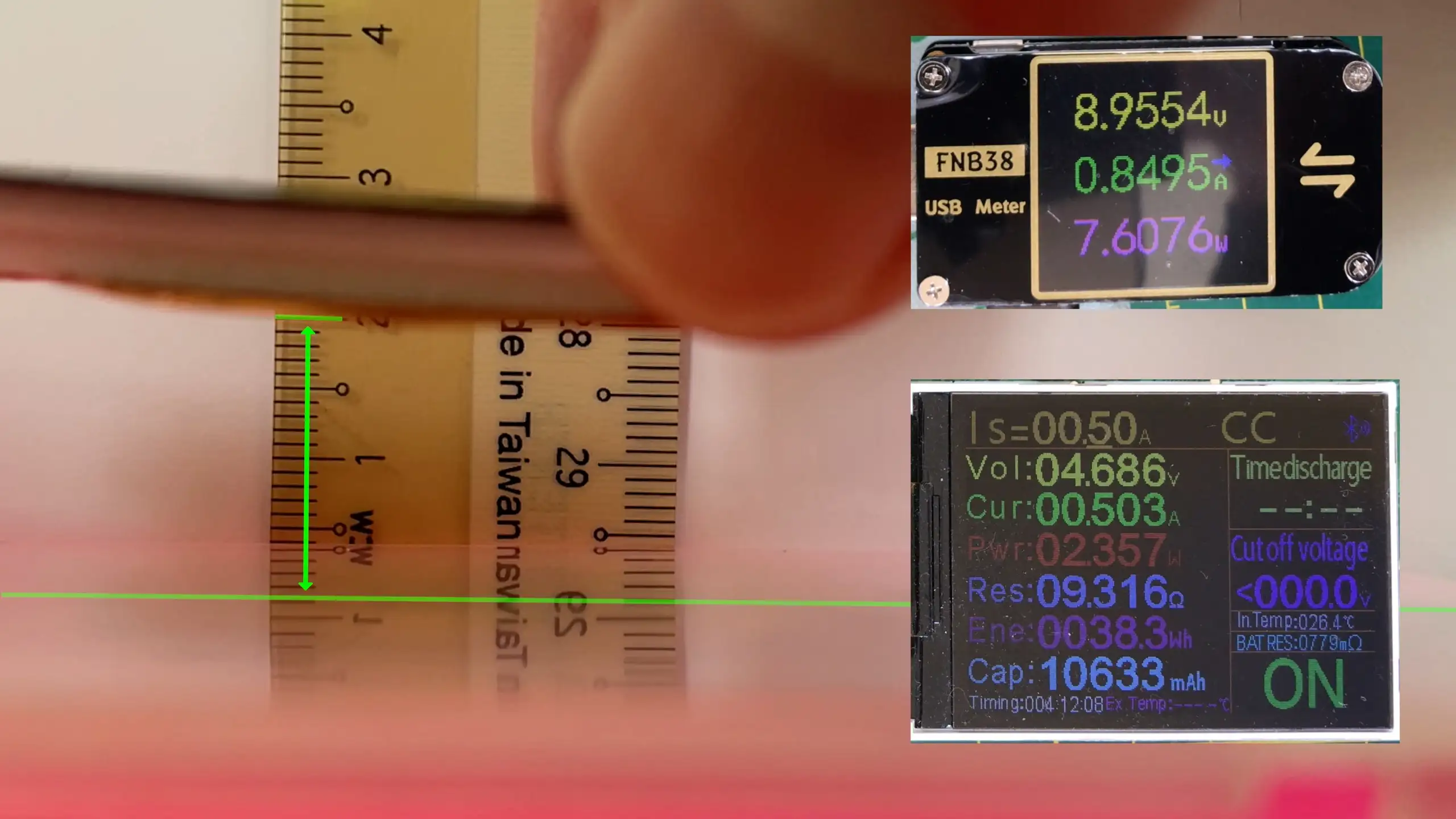
The transmitter board I have can take 5v, 9v and 12v as input and in theory with the receiver board I have we should be able to get up to 1.5A at 5v out of it. To test this I’ve hooked the transmitter up to my USB power monitor and the receiver up to my electronic load. The USB power monitor is pretty cool, it will monitor the voltage, current and power, and it also lets me trigger the various USB Power Deliver and Quick Charge modes.

Testing the wireless charging PCBs

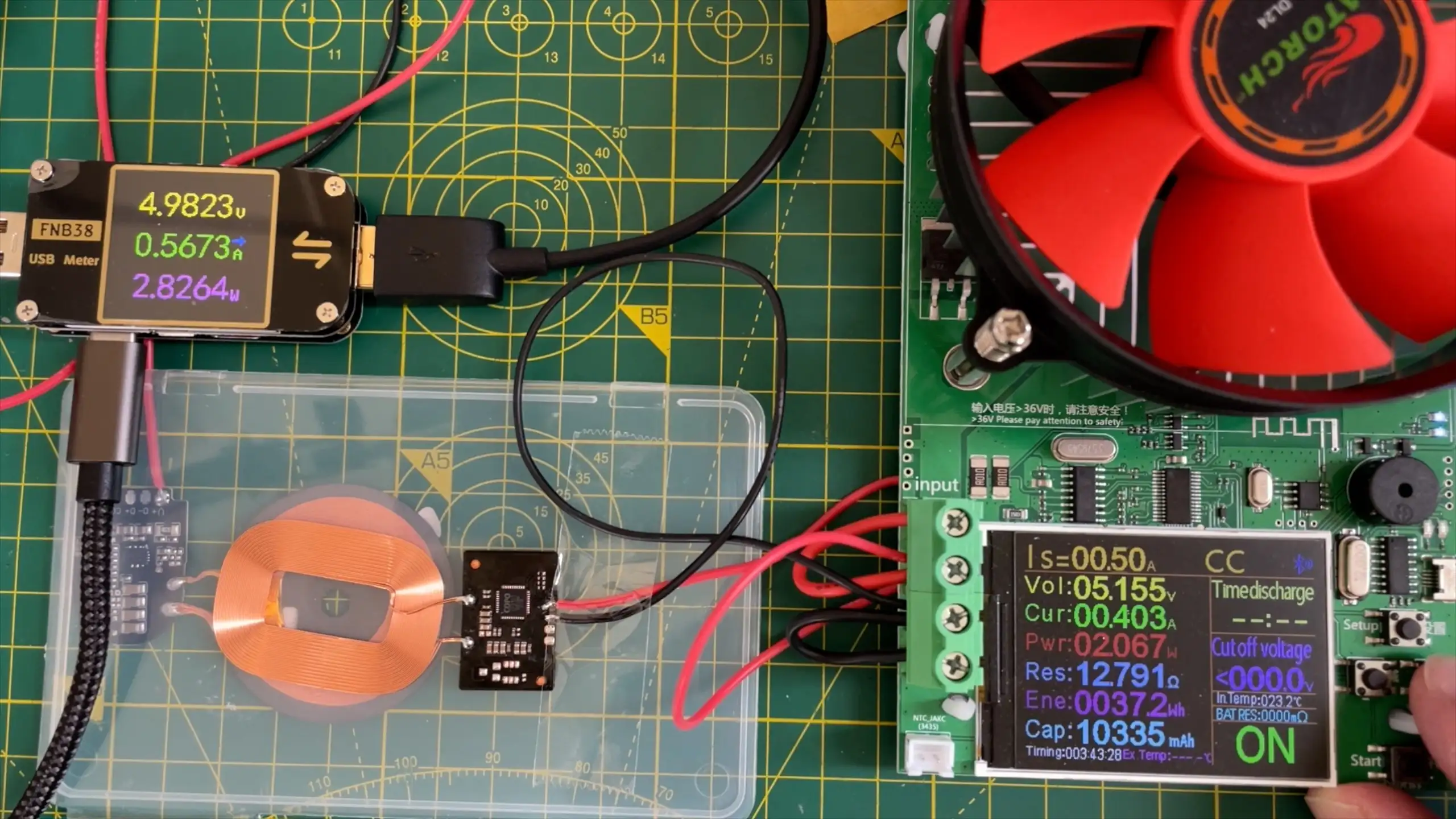
I’ve run through the three different voltage inputs with the electronic load set to different load currents and generated the following graph. What was quite interesting is that I struggled to get the 12v input to work consistently, it would often fail at quite low current loads.

Wireless charging PCBs graph

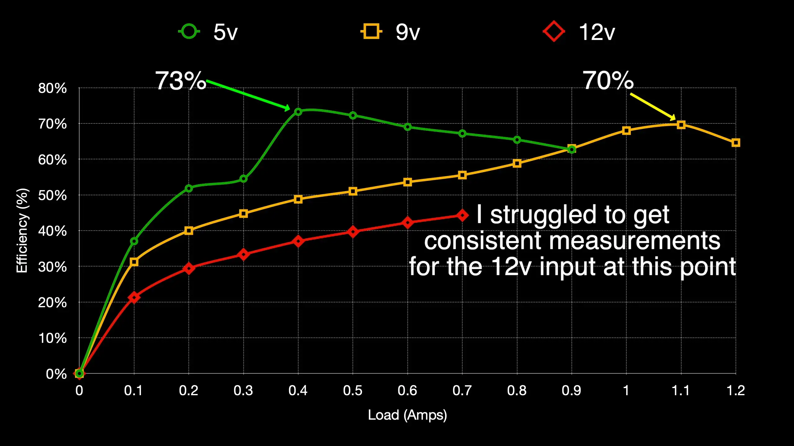
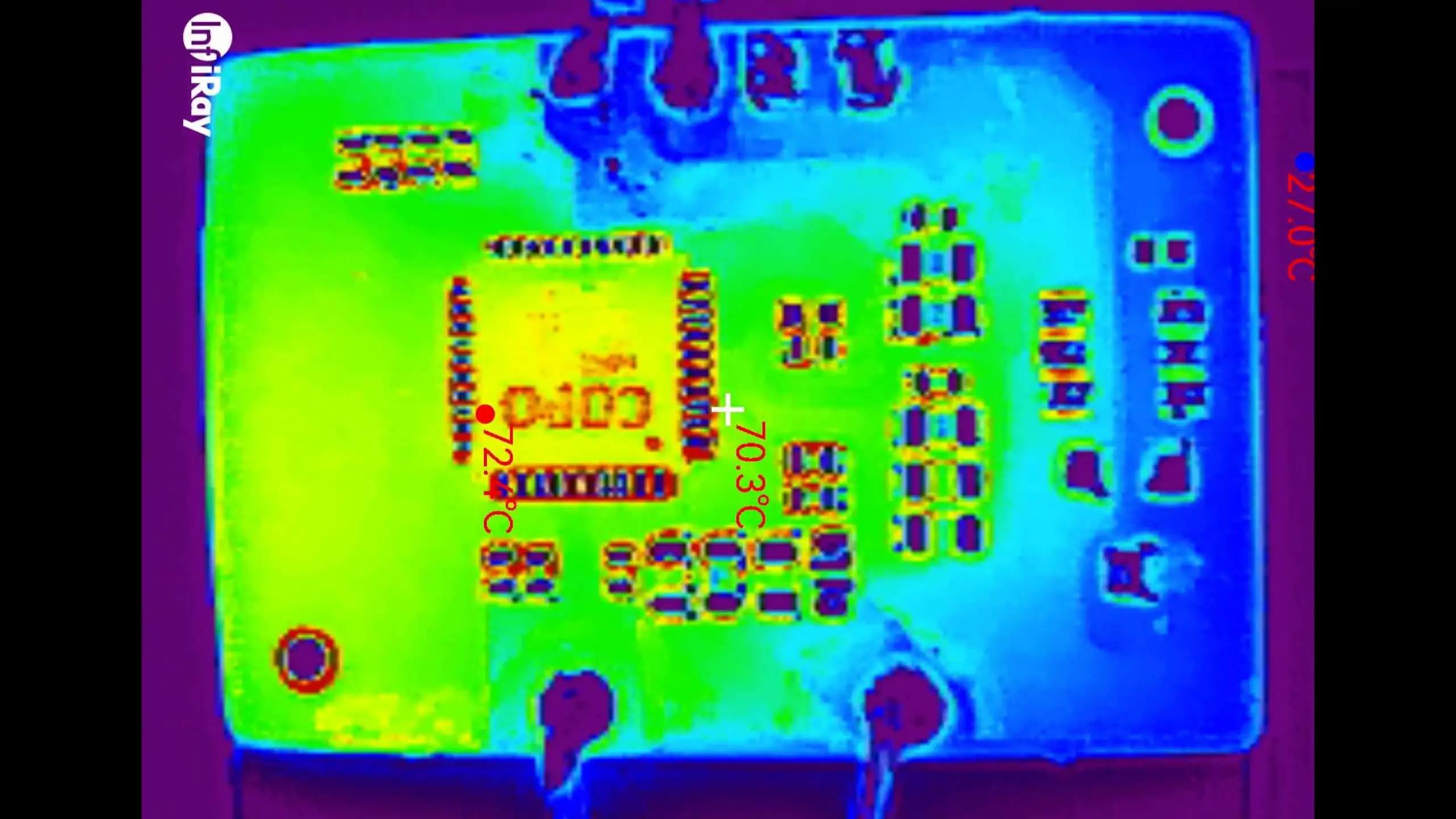
With the 5v input, we get maximum efficiency of 73% at a load of 0.4Amps. With the 9v input, we get just under 70% efficiency at 1.1 amps. With the 12v input, I couldn’t get it to work consistently above 0.7Amps and the efficiency was very low. I also noticed that the receiver board was getting quite warm when the transmitted was using 12v. The board was getting up to almost 80 degrees C, which is a bit too hot for my liking. When running at 5v or 9v it only got up to about 50 degrees C.

Temperature of Receiver Board

The efficiency I’m measuring is pretty close to the listing on AliExpress - which says we should be able to get 75% - so we are facing one of those rare occasions where the listing is actually accurate!

I also tried to measure the range of the transmitter and receiver. Running at 5v I got around 1cm of range, at 9v I got around 1.5cm - 2cm of range. I didn’t try and measure the 12v range as I didn’t really trust it.

5v Range of Wireless Charging PCBs

9v Range of Wireless Charging PCBs

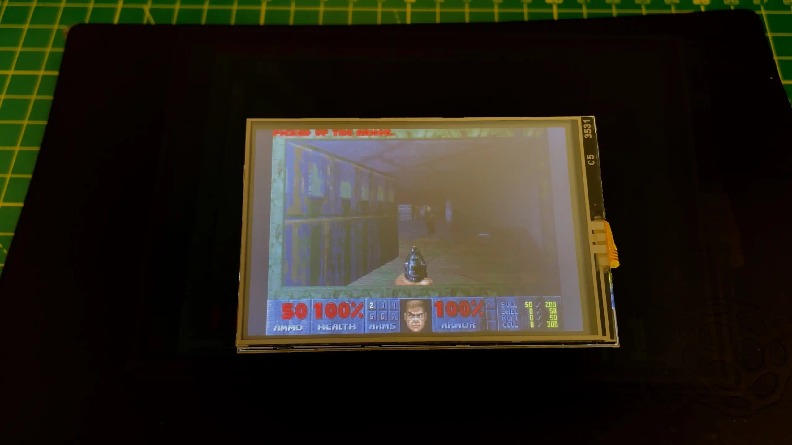
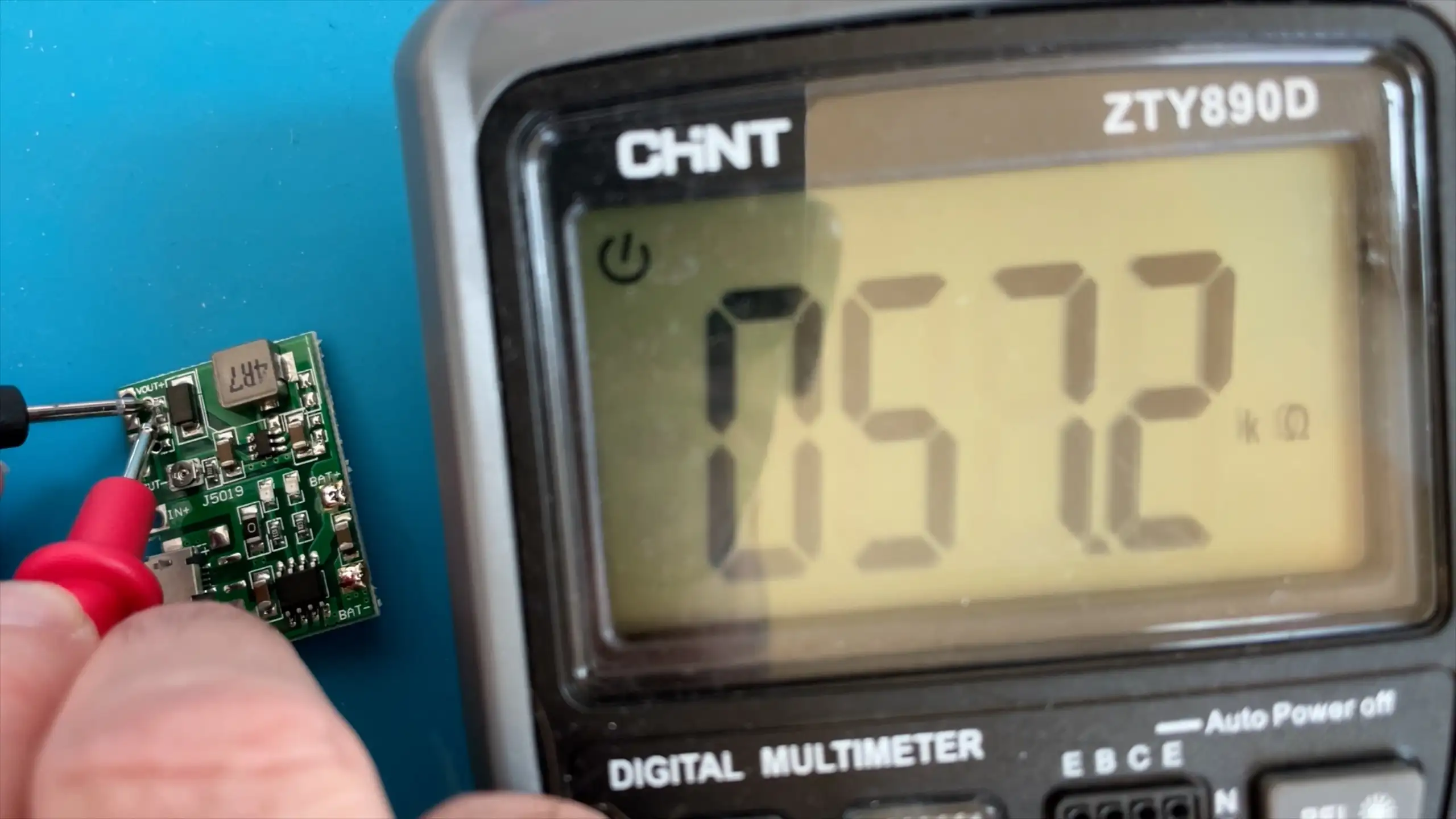
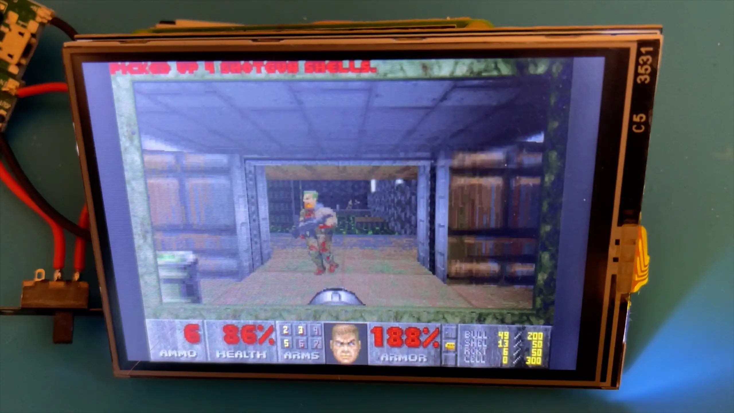
I thought it might be fun to try and run a Raspberry Pi Zero W2 with the transmitter and receiver boards. To make it a real test I’m going to run Doom on the Pi with a nice TFT screen. To check if this was even feasible I ran the Pi with it connected to my USB monitor and it peaks at around 0.65Amps when running Doom. So it should work without any problems.

And after a bit of fiddling it works really well, we can run the Pi over wireless power.

Wireless Pi Doom Machine

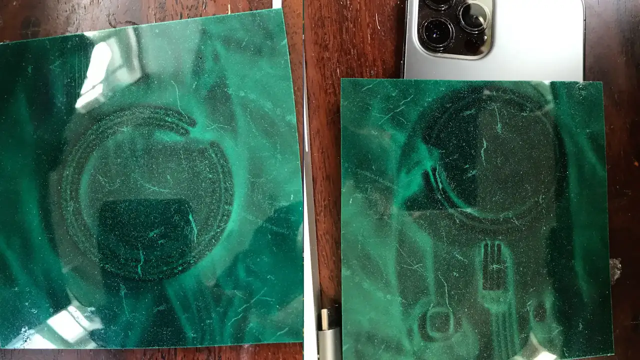
One of the things I did find, is that it’s surprisingly hard to get good alignment of the coils when you can’t see the transmitter. This does explain why the iPhone has a bunch of magnets in it to help line it up with the transmitter. I’ve used one of my magnetic sheets to visualise the magnets in the phone and phone charger.

iPhone Magnets

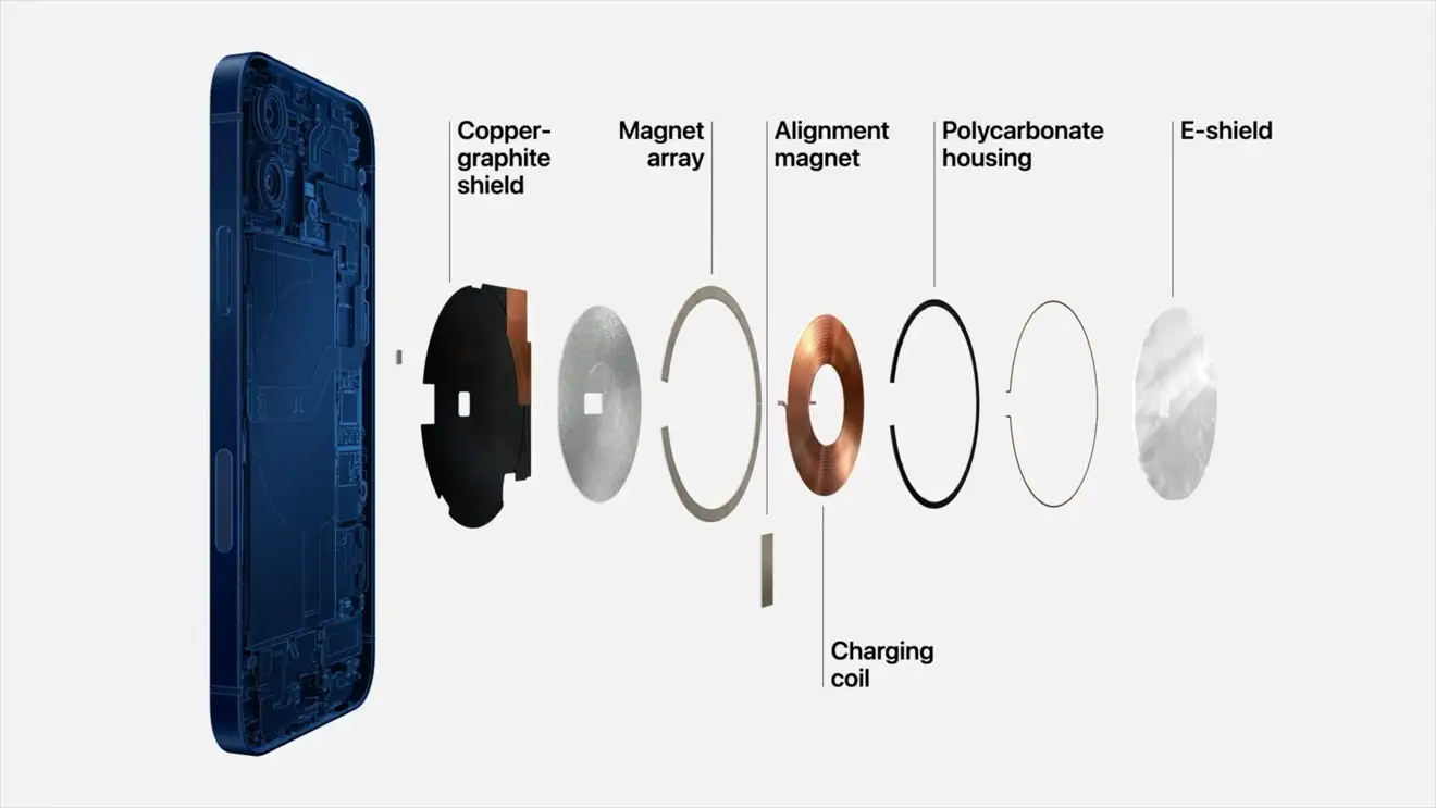
There’s also this nice exploded view of the iPhone showing the magnets.

iPhone Exploded View

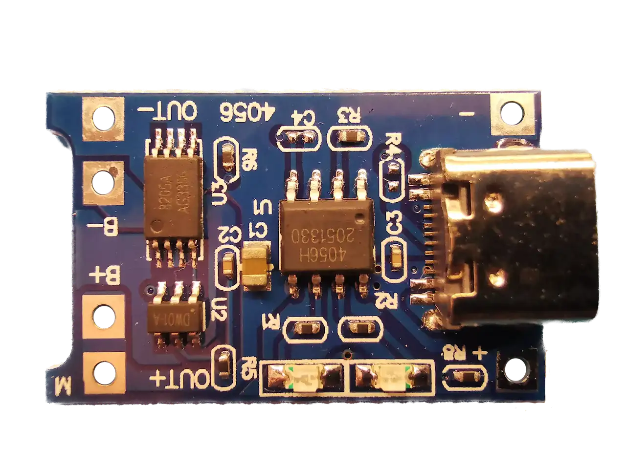
So, it’s pretty cool to power the Pi completely wirelessly, but it is ultimately a bit pointless. As soon as we move the Pi away from the transmitter coil it stops working. We really do need to actually have a battery that is charged by the receiver. I’ve got a whole bunch of battery charging boards based around the TP4056 chip.

TP4056 Battery Charging Boards

But I’ve also got a bunch of boards that use the TP4056 chip and have a built-in boost circuit. The potentially nice thing about having a boost circuit is that our battery can go very low and we’ll still be able to use it to power the Pi.

TP4056 And Boost Circuit

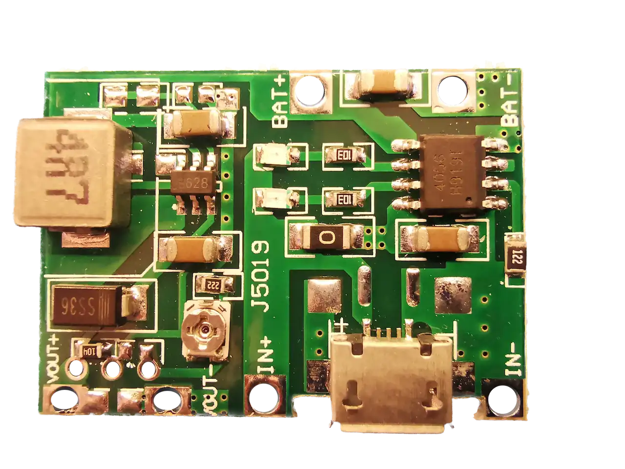
Unfortunately, the first board I tried boosted the battery voltage without any problems, but I could only adjust it to 5.66 volts. The Pi’s power management IC can only take up to 5.5 volts, so although we’re close, I’d like to give it 5v - I really don’t want to blow up my Pi as they are still quite hard to get hold of!

Looking at the boost converter’s IC datasheet, the voltage is controlled by this resistor divider.

Boost Converter Resistor Divider

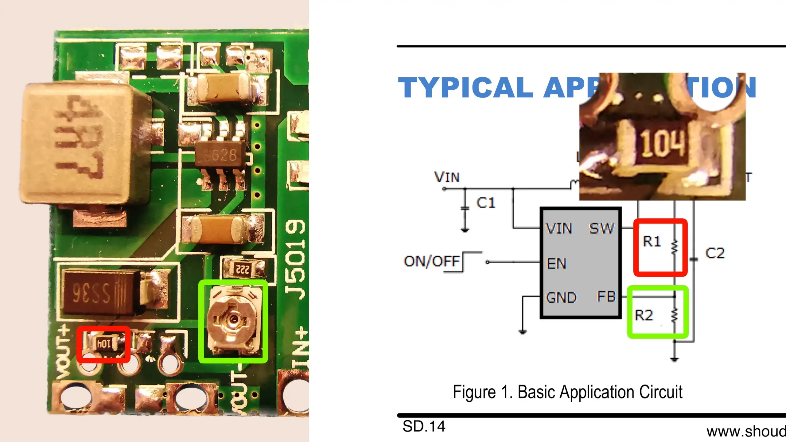
The top resistor has the code 104 - which should be 100K ohms. But when I measured it in the circuit I only got 57K. The trim pot is also only going down to 9.9K - so there’s no way we can get the voltage we need.

Wrong Value

Fortunately, we can add some additional resistors to the board, so I’ve ended up soldering a 100K in parallel with the top resistor. With this in place, we can get 5v out of the boost converter.

With the battery hooked up, it charges up via the wireless transmitter. And eventually the battery gets up to full charge.

It’s now easy enough to hook it up to the Pi with a switch to turn it on and off.

Wireless Pi Doom Machine

Of course, with it all working, I realised it would probably be much better to split the charging and boost board into two separate modules. We can then easily switch off the boost converter. If we then it will drain the battery over time. But that’s something for another day when we’ll add sound and a controller to make the ultimate wireless Pi Doom machine!

There’s a full video of this blog post available here - it’s worth a watch as there’s a lot more detail in it.

You can buy the Infrared camera I’m using here.

The nice USB power meter is this one: AliExpress, Amazon.

The wireless power transmitter is this one.

And the receiver is this one.

#DOOM #EFFICIENCY #PCBS #RASPBERRY PI #VOLTAGE INPUT #WIRELESS CHARGING #WIRELESS PI DOOM MACHINE

Related Posts

DIY 20,000mAh Power Bank - Was it worth it? - In this blog post, I embarked on a fun project to create a DIY power bank using two 10,000mAh lithium cells I had lying around, and a charge control board. After some tinkering and tests, I learned that measuring power bank efficiency requires more than looking at amp-hours. With some help from a friend, I found out our power bank was actually over 93% efficient, a pretty fantastic result. Despite some challenges with certain devices not drawing their full potential power from my power bank, I concluded that while it was an enjoyable project, buying a ready-made power bank might be more convenient.
Scripting KiCad to make coils - I've been diving deep into the world of PCB (Printed Circuit Board) coils, inspired by Carl Bugeja's incredible PCB motors! After deciding to set up an automated process for creating the coils rather than manually drawing them (can you imagine?), I found our main constraints became track width and spacing, and the number of layers we could use. During the process of creating spirals for our coils, I encountered some interesting problems - spirals are easy, but what about arbitrarily shaped coils? My attempts ultimately lead me to develop more efficient algorithms and KiCad plugins to generate these special coils. A rewarding challenge of math, programming, and electronics! My code has been published on GitHub, and I’m eager to see how others might make use of it!
Minimalist Microcontroller: Building a Bare-Bones Dev Board - In a thrilling DIY endeavour, I attempted to build the most minimalist ESP32 dev board possible. Diving deep into the schematic of the ESP32 S3 WROOM module, I chopped out the non-essentials and whittled our needs down to bare bones. The experiment saw me juggling USB data lines and voltage regulators, waving goodbye to an array of capacitors and connectors and boldly embracing the simplicity of direct connections. Despite a few hitches, the miniature Frankenboard came alive, proving that sometimes less is more...at least in the world of microcontrollers.
I Need More USB Power! - I've been accumulating more and more USB powered devices for my workbench lately, and my single 65W USB-C supply just isn't cutting it anymore. So, I've decided to source a new solution. After some digging, I stumbled upon a remarkable board on AliExpress with four USB standard sockets and four USB-C ports, which support just about every protocol there is! Oh, it easily delivers a solid 65 Watts. With this, I am finally able to fully power my gear. From mini hotplates to soldering irons, my workbench is more juiced up than ever!
ESP32 TV Version 3 - In the latest board revision, I've successfully resolved some key issues, including a USB interface conflict between the USB2244 and the ESP32 and a risky battery charging mistake—no more direct USB 5V to the battery! Plus, I managed to wrap this up without any clumsy bodge wiring. I've even introduced a new feature: a microphone is now on board, setting the stage for some exciting future projects. Stay tuned for what's coming!

Related Videos

Wireless Powered Raspberry Pi - Dive into the magic of wireless charging technology with a Raspberry Pi Zero W2 and a TFT display! Discover how it manages to power up and run Doom without an obvious power source. Explore the efficiency, power input and output, temperature dynamics, and range of the transmitter. Furthermore, learn about the issues with locating magnets for alignment and possible solutions for ensuring a consistent power supply, including a complete wireless charging system with a battery.
Happiness is a Working Blink Sketch - ESP32-S3 PCBs Are Here! - In this video, I explore the functions of my newly arrived little boards - essentially a PCB that an esp32 S3 room module can be connected to. I put the board's voltage regulator, battery charger, and a 3 watt class D amplifier to the test, and damn, they work perfectly! I even use breadboards, connecting them together to facilitate a wider workspace. I gave the pcbs a spin, conducting sanity checks to ensure full functionality. With a successful battery charge and impressive voltage measurements, my PCB's are up to the challenge. I also dabble in some circuit jargon, explaining schematics, amplifiers, battery chargers and a clever mosfet approach. To top it off, I solder on an ESP32 module and prove that yes, it actually works. Stay tuned for a following video where we'll work with a speaker and display!
Simple Multi USB-C Power Module - With my growing list of USB-C powered devices and just one cable, I found myself underpowered on my bench. My solution? Scouring the depths of AliExpress for USB-C power delivery, QC2, and QC3 step-down converters. After initially purchasing individual boards, I struck gold with an ultra-convenient 4-in-one board. Paired with a Meanwell power supply, I enjoyed pushing my new setup to its limits with the MiniWare electronic load tester. Although managing to pull a decent 65W, I'm dreaming up a 3D printed enclosure and eyeing up MiniWare's display modules for future improvements. I reckon, while I'm battling delayed PCBs and dodgy components, it's certainly a fun way to help power up my bench!
DIY Power Bank: 20,000mAh? - Discover the efficiency of a DIY 20,000mAh USB-C power bank compared to commercial versions, as a control board and lithium batteries charge up an array of devices, including a soldering iron and mini-hotplate, while also considering the project's overall cost.
Lots of Stuff - And a NEW PCB! It's a rare mailbag video. - In today's episode, I'm unboxing some goodies from PCB way - my super tiny esp32 breakout boards, which I'm planning to use to recreate a mini TV complete with speakers and a display. Also received some convenient adapter boards for easier testing. Excited to explore a new Arduino Nano esp32 based on a different, tinier module, and contrasting it with other products like the Tiny Pico. Also up for testing is a new mini wear electronic load compared to my old one, and an ATX power adapter for more USB ports. I'll be testing power banks, playing with inexpensive yellow displays and nunchucks for fun gaming projects, and testing out an RGB bead curtain with hackable possibilities. Also, under my ongoing experiments is a Raspberry Pi zero, turning into a 'Doom' playing device with added sound and game controllers. Finally, an air quality measuring device for detecting air particles, CO2 levels, humidity, temperature and other parameters is up for exploration as well. A whole array of fun projects queued up, so stay tuned!
HELP SUPPORT MY WORK: If you're feeling flush then please stop by Patreon Or you can make a one off donation via ko-fi
Want to keep up to date with the latest posts and videos? Subscribe to the newsletter
Blog Logo

Chris Greening


Published

> Image

atomic14

A collection of slightly mad projects, instructive/educational videos, and generally interesting stuff. Building projects around the Arduino and ESP32 platforms - we'll be exploring AI, Computer Vision, Audio, 3D Printing - it may get a bit eclectic...

View All Posts