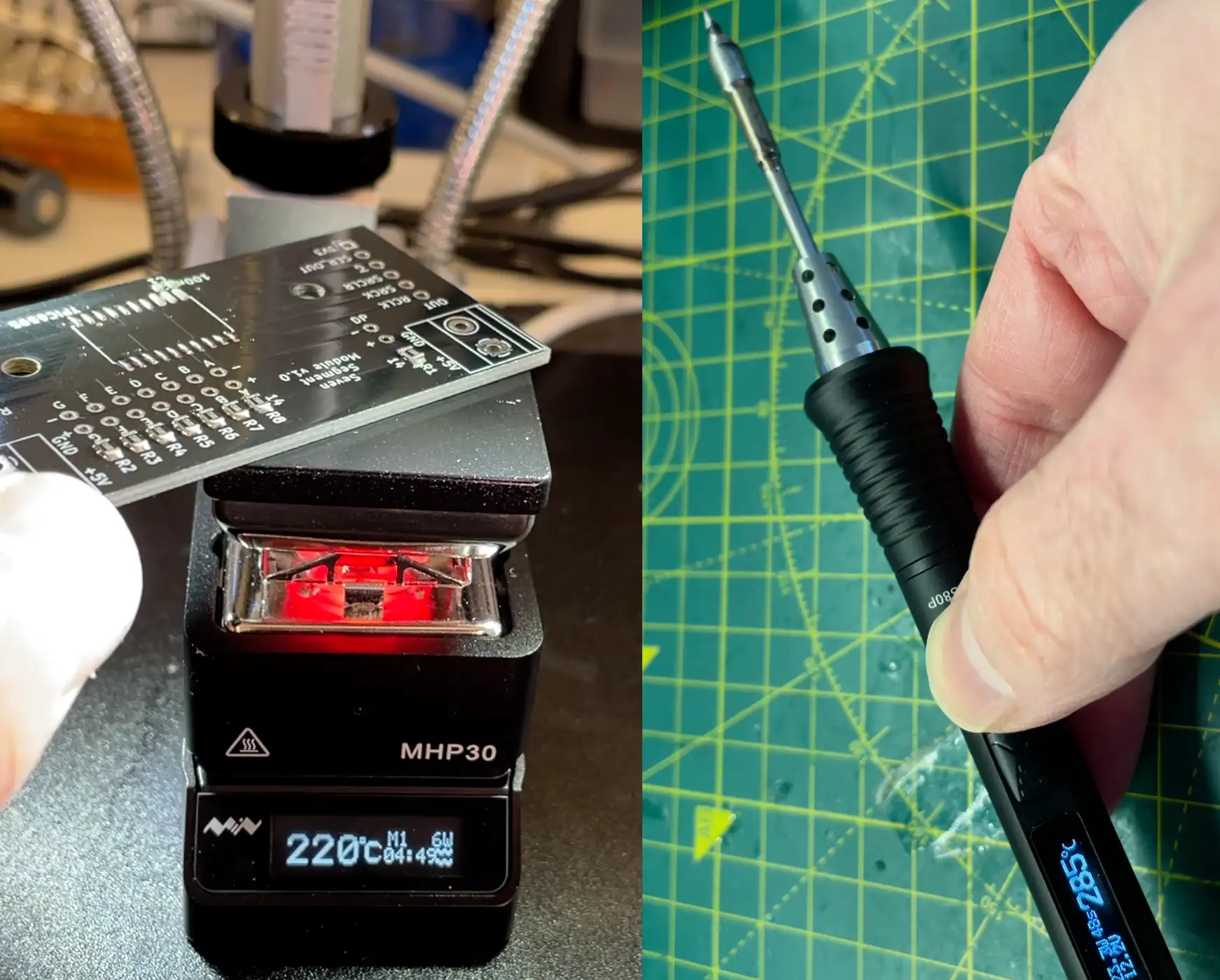
I’ve been accumulating a lot of USB-C devices, it started off with the Mini Hotplate and now I’ve also got a TS80P soldering iron.
If you prefer video content, you can see the full video walkthrough here.
Both these devices have a USB-C input and take advantage of the various quick charge and power delivery options to get the most out of their power supplies.
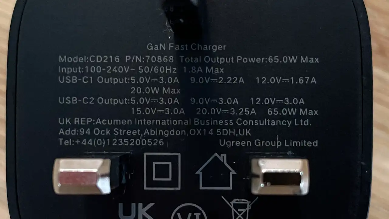
I have got this really nice Galium Nitride 65W USB-C power supply, but it would be nice to be a bit more portable sometimes, particularly with the soldering iron.
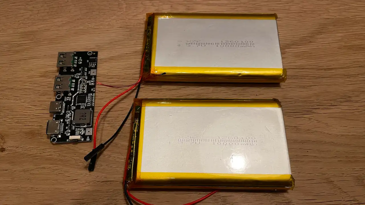
Now, I could go out and buy a power bank - that would be the most sensible thing to do - but I’ve had a couple of 10,000mAh lithium cells lying around for a year now. So I thought I might as well buy a charging board to go with them and make a DIY version.
The board I’m using states that the batteries need to be able to supply up to 10 amps, so I thought we should probably check that first.

Unfortunately, wiring up the battery to my electronic load didn’t give very promising results - we only got 3 Amps before the batteries cut out. Even with two of the batteries in parallel, we’ll only be able to get 6 Amps in total - nowhere near enough.
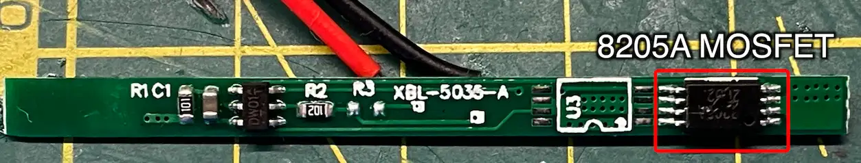
My initial suspicion was that this was due to the battery protection boards being a bit too protective. With these types of battery protection boards, it’s actually quite complicated to work out what the actual current limit is - it’s not just a simple resistor. You need to look at the MOSFET and see what its resistance is when it’s turned on. It’s the voltage drop across the MOSFET that is used to detect the over-current condition. The MOSFET on these battery protection boards we have about 0.25mΩ of resistance - which means we can only get about 3amps.
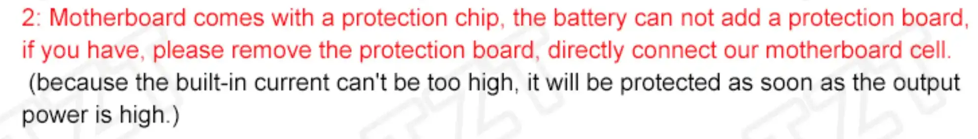
Fortunately, along with the 10 amp requirement, we also have these instructions telling us to remove any battery protection as it’s all built into the board.
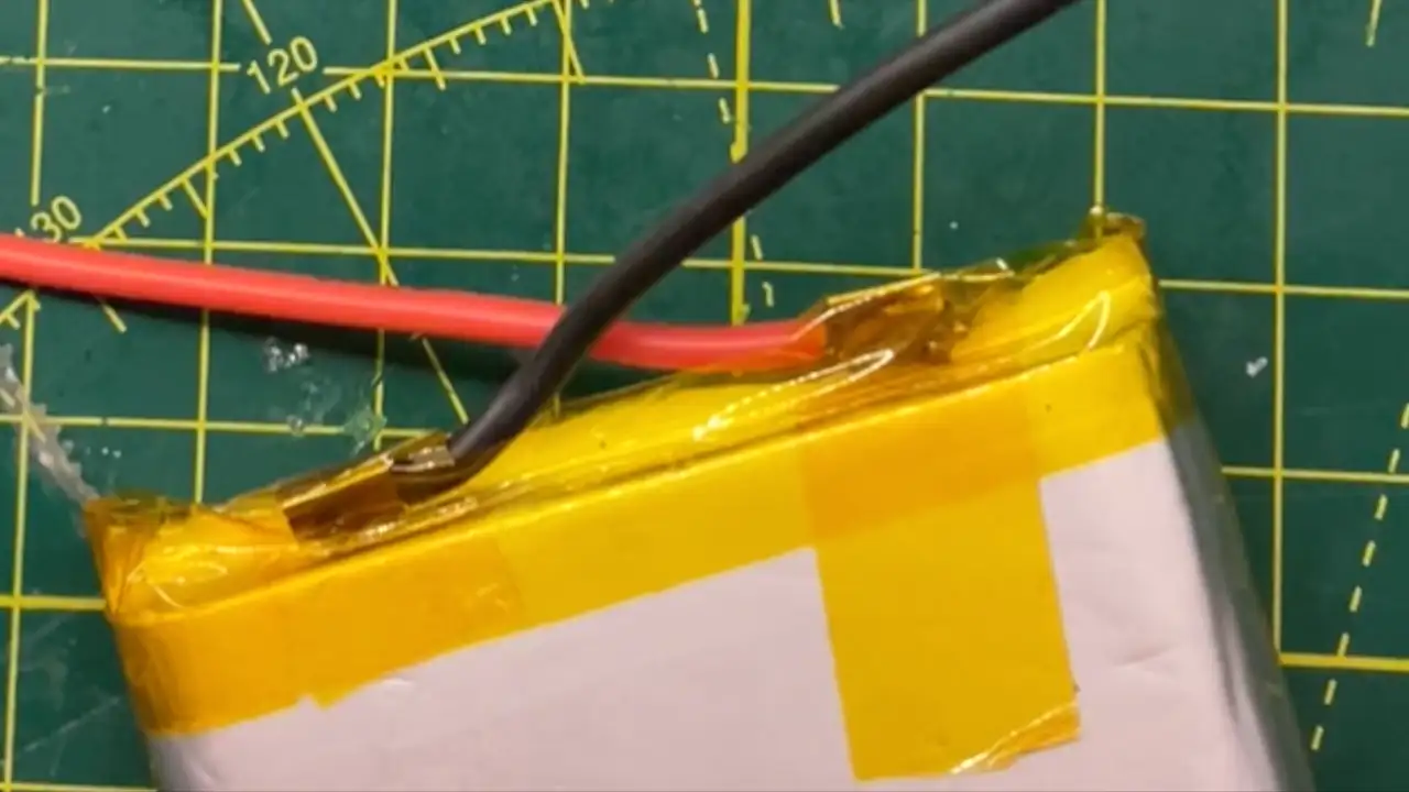
It’s surprisingly easy to do this, we just need to unwrap some of the Kapton tape and then the battery protection board can just be desoldered.
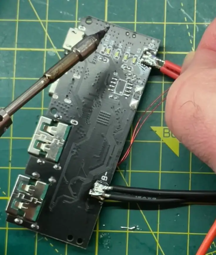
Removing the battery protection board also lets me solder on some much thicker and more flexible wires. The ones that came with the battery were pretty thin and stiff.
Wrapping it all back up with Kapton tape - we have the perfect crime - no one would ever know.
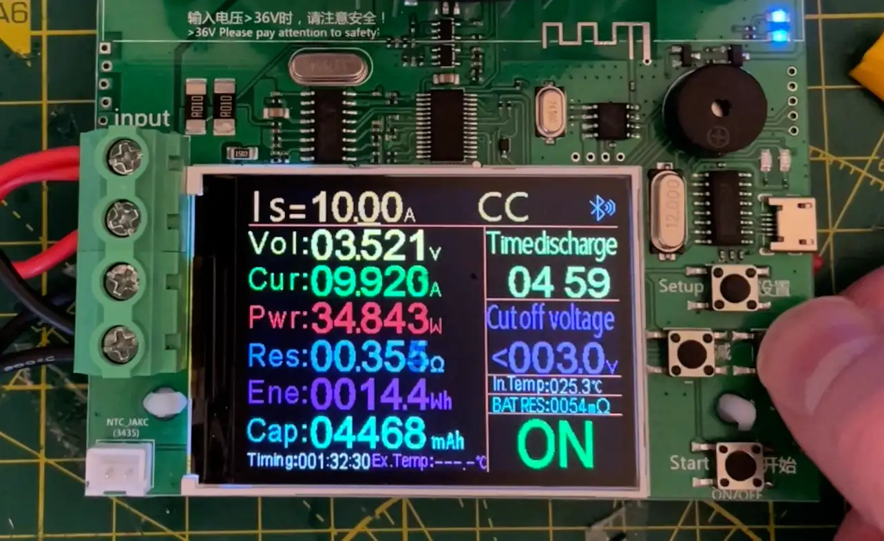
With the protection board removed, we can easily get up to 10amps from a single battery. We can even go much higher if we wanted, but 10 is plenty. With the two batteries in parallel, we’d get a whopping 20amps.
Connecting the batteries to the board is pretty simple. You can safely wire up lithium cells in parallel provided they have the same capacity - they will just self-balance during charging and discharging.
I did make sure before connecting them that I’d discharged them to around the same voltage so there wouldn’t be any big current surges between them.
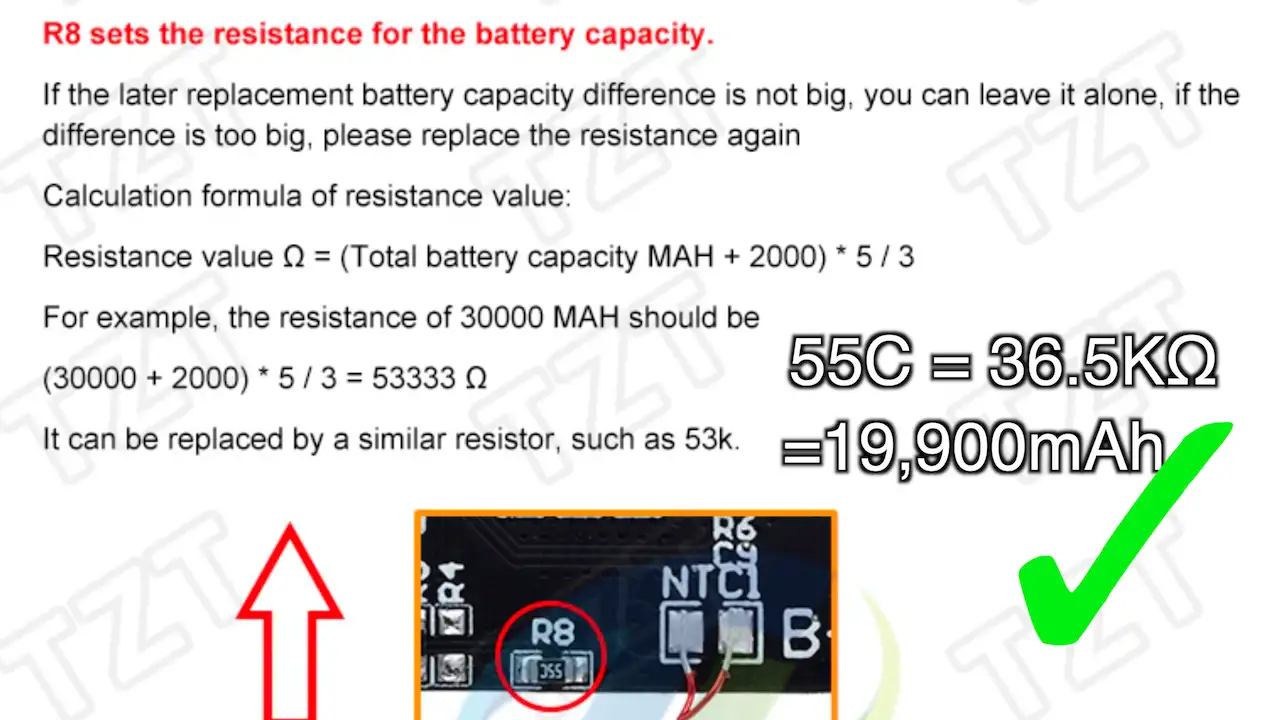
The control board does have a resistor to set the battery capacity. Fortunately, my board is already configured for 20,000mAh, so there’s nothing for me to do.
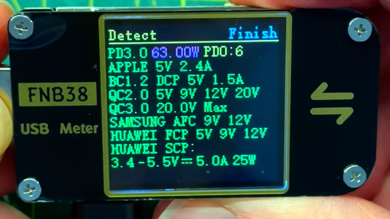
It all charges up nicely. The control board is pretty nice and it takes advantage of the various fast charging options to take the input power up to 21W and speed up the charging.
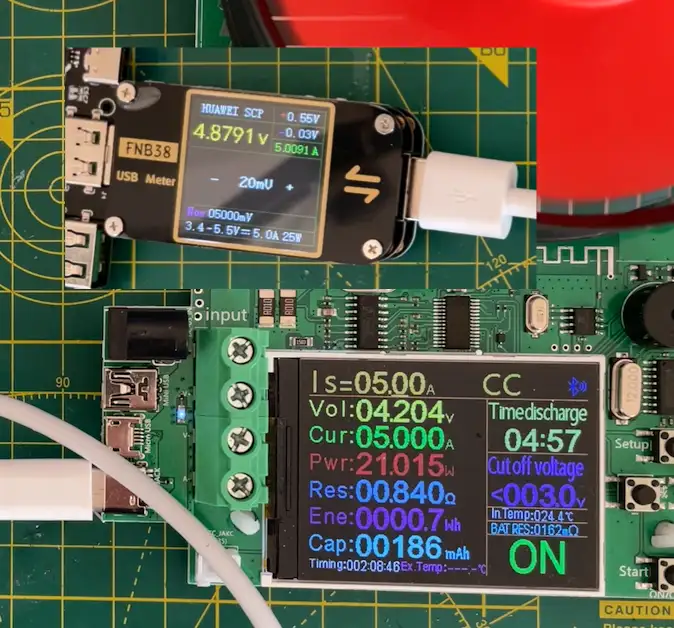
Hooking it up to my electronic load - the maximum current I can pull by default is limited to 3amps - trying to go above that triggers the board to shut down.
However, I can use my USB power monitor to switch to Huawei’s Super Charge Protocol which gives us 5amps. Not bad at all.
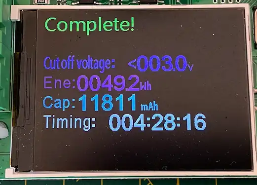
Unfortunately, after the discharge was complete we only measured 12,000mAh - that’s quite a bit lower than I was expecting. But we did have the USB power monitor in the circuit which will have had an impact.
I recharged the batteries and tried again.
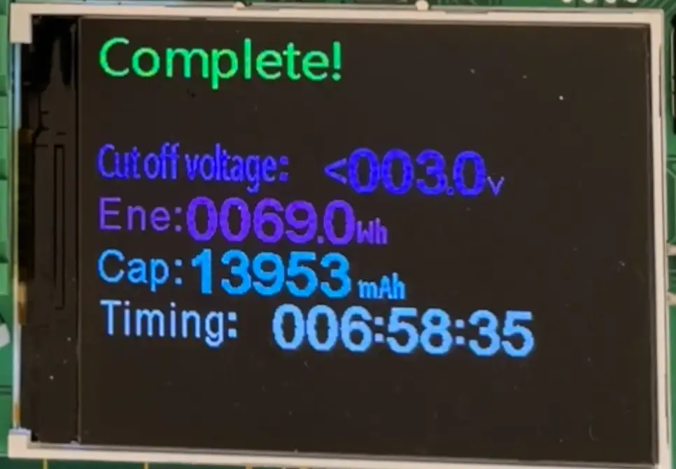
Unfortunately, this produced some very similar results - just under 14,000mAh over 7 hours.
I started to wonder if maybe my batteries were not 10,000mAh after all - there is quite a suspicious review on a similar listing on AliExpress for the same batteries.

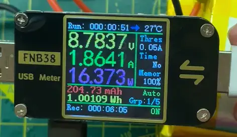
I did what I should have done in the first place. I fully charged the batteries and measured the actual capacity.
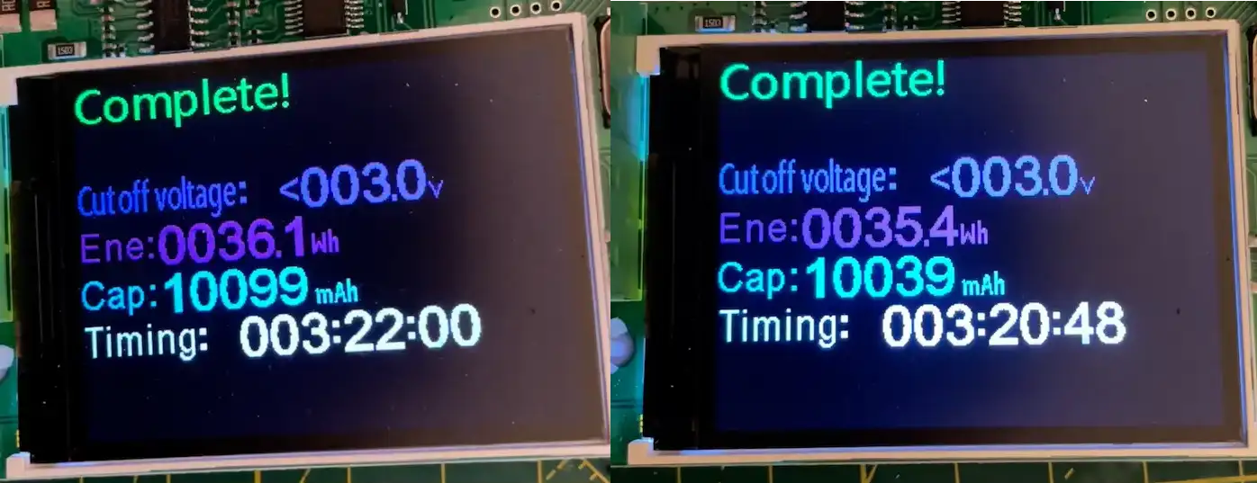
And the results for the first battery are: 10099mAh - it’s bang on the money. And it’s a similar result for the second battery: 10039mAh.
It turns out the batteries I got from AliExpress are really good - I owe them an apology.
We’ve got 20,000mAh capacity, but we’re only getting 14,000mAh out - does that mean our power bank is only 70% efficient? If true, that would be really rubbish - especially as the datasheet claims up to 96% efficiency on the boost output.

Well, it turns out that as always things aren’t that simple and I was making a schoolboy error.
When looking at power bank efficiency we should be looking at the energy and not the amp hours.
There’s a great website here that explains this in detail - worth a read if you’ve ever wondered why your power bank doesn’t seem to be as good as it should be.
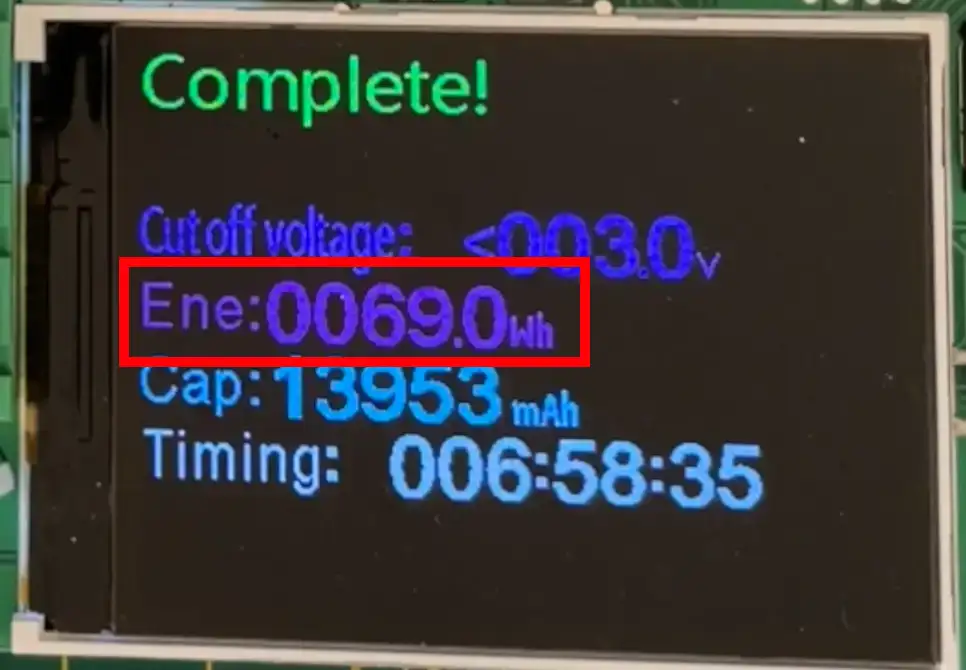
Our two batteries give us 20Ah, and they have a nominal voltage of 3.7 volts. That gives us 74Wh of stored energy. Eagle-eyed readers will have seen that as well as the mAh value our discharge monitor also gave us the watt-hours - we measured 69 watt-hours of energy on the output - this means our efficiency is actually over 93% - that’s a pretty good result. Our power bank is actually very good!
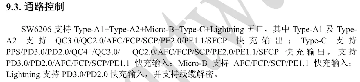
Now, this shouldn’t really be too surprising. The actual control board is pretty amazing - there’s really nothing on it all the heavy lifting is taken care of by this one chip - the SW6206 - so you would have to really mess things up to make it not work.
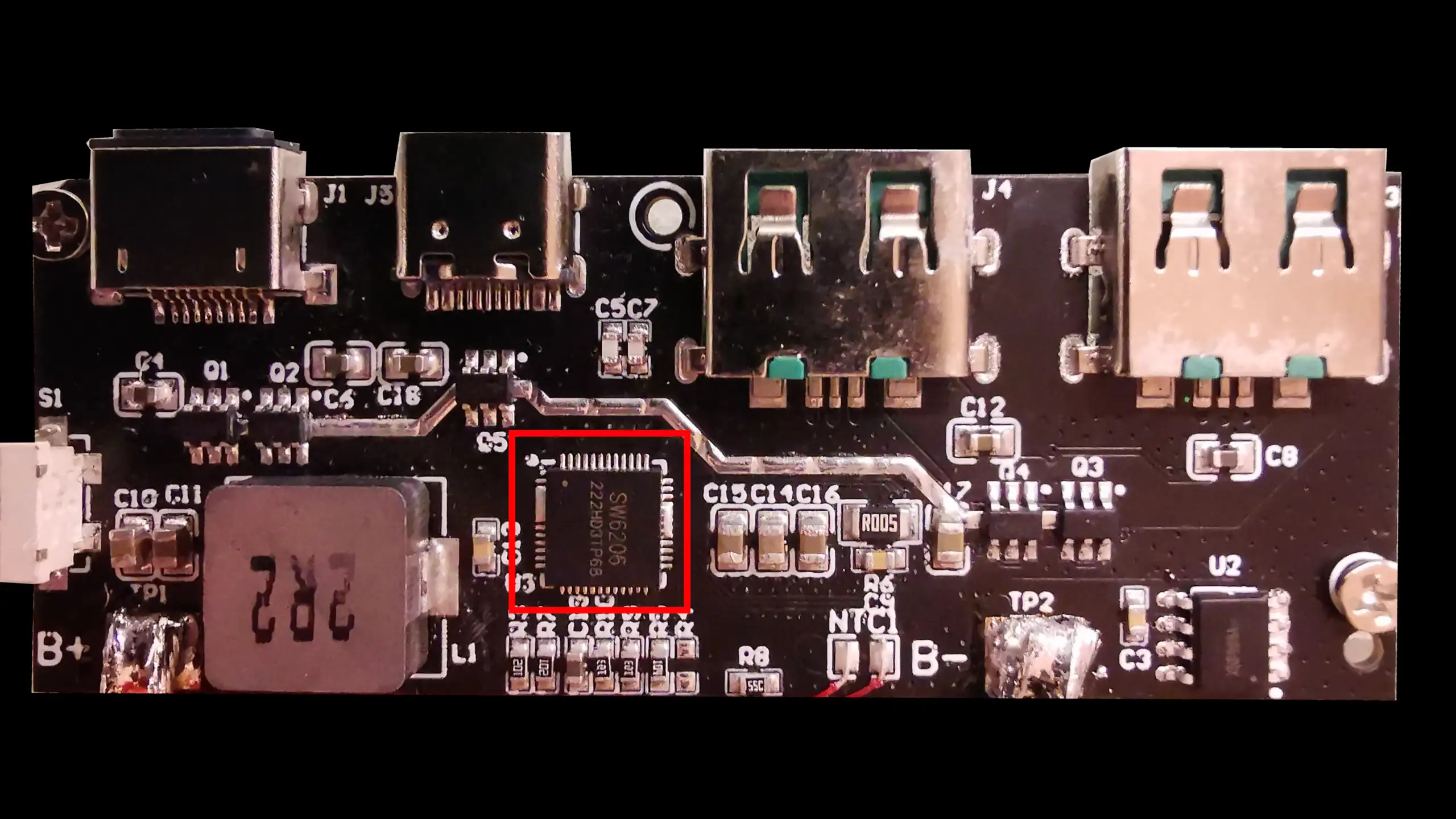
The IC supports a completely bonkers number of output options - absolutely amazing.
The other ICs are just MOSFETs for controlling the outputs and a single-chip battery protection IC - the XB8089A.
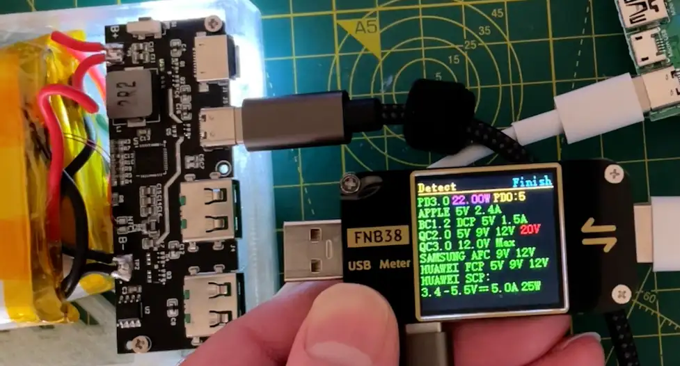
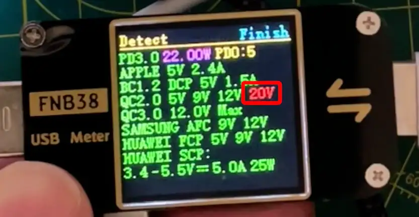
We can test the output options using my USB power monitor - these are really handy little devices and you can pick them up for not very much money.
On the USB-C output, we get these options.
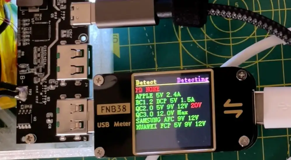
And on the USB-A outputs, we have these options.
The only slightly annoying thing with the power bank is that it has the usual auto shut-off function - if not much current is being drawn the power bank turns itself off. You can put it into a constant output mode by holding the button, but then the power delivery options don’t seem to work.
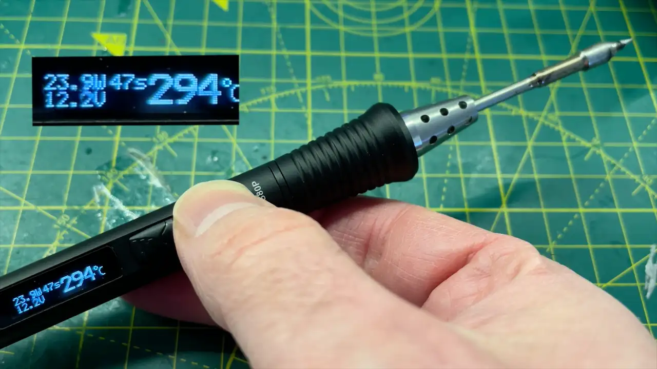
Trying out the TS80P soldering iron - it works ok. On the USB-C output, it only uses 9v which is ok - but it’s not fantastic. But on the USB-A outputs, we get up to 12 volts which is the maximum voltage the TS80P can run at - so it will work nicely.
The Mini Hotplate is not as promising - with my Galium Arsenide power supply, it will draw 20V and heats up really quickly. But with my power bank, it will only draw 12 volts - so it heats up quite slowly.
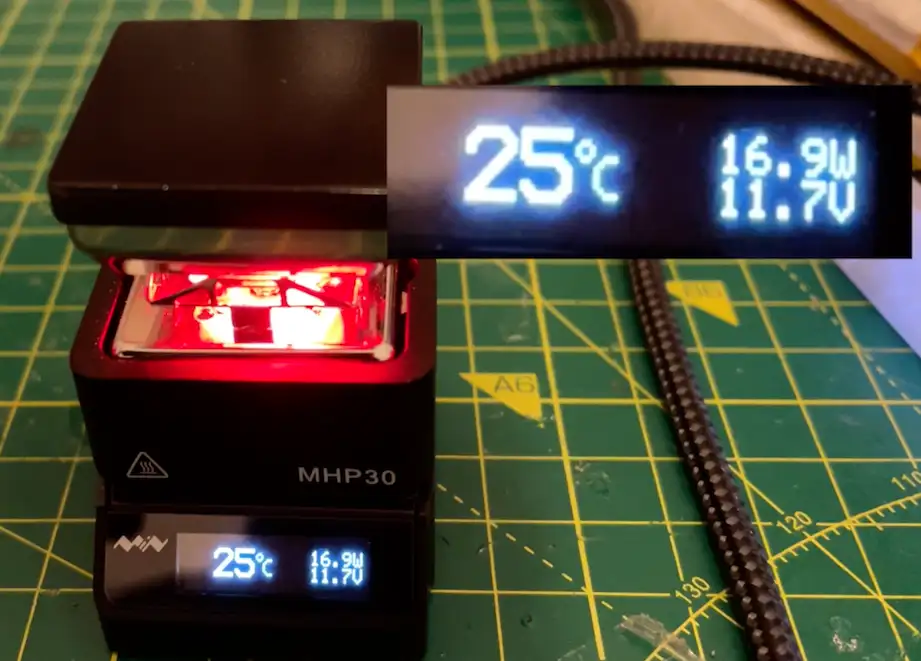
Now of course - this is not that surprising, it matches what we saw with the USB tester and it matches the spec of the control board - it only goes up to 12V on the output.
On the question of DIY vs Buy - was it worth it?
Including shipping, the cost for the batteries was around 17 pounds, and the charge control board was 4-5 pounds. So our total cost was around £22.
This comes out slightly cheaper than some of the commercial versions on Amazon. So I think it’s a bit of a toss-up - it’s a fun project, but you would probably be better off just buying one.
There are 65W power banks available that would be able to run the mini hotplate at full wack - they are slightly more expensive - but maybe an extra 10-20 pounds or so would be worth it.
There is a nice 100W control board on AliExpress that I think is worth investigating - it’s a bit more expensive, but it’s a lot more powerful. The only downside is that it only has one USB-C output.
You can get the components I used from these links:
- Batteries
- Power Bank Control Board
- USB Power Monitor
- 100W Power Bank Control Board
- DL34 Load Tester Amazon or AliExpress