I recently received this email from Amazon - at some point I hooked up some of my Hue devices to our Alexa and must have clicked a button to remind me to order supplies.
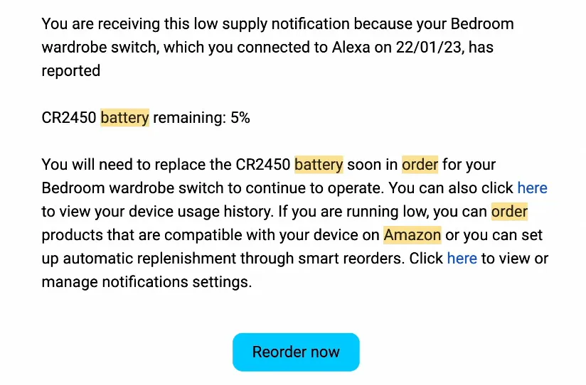
I find it pretty amazing that the Hue switch in question was actually ordered in 2016, so the battery has lasted around 7 years!
What was very interesting, to me, was the link to view the device usage history. Clicking on it takes us to this page:
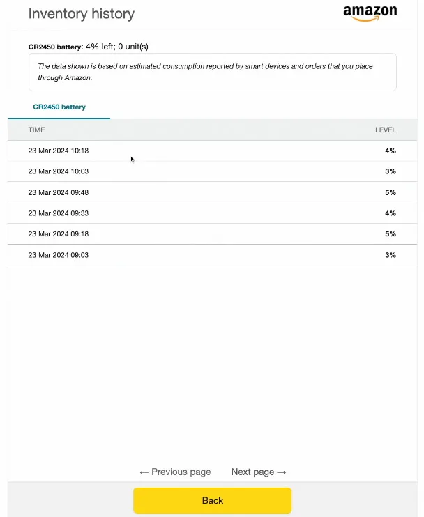
It’s an interesting table, but not very useful - we can’t do much with this table. However, doing a bit of snooping on the network traffic, we can see there’s some fairly simple data being sent around when click the Previous and Next page links.

After a bit of chatting with Mr ChatGPT I was able to turn these requests into a little web scraper. All we need is a valid cookie from one of the requests and we can pull down all the data.
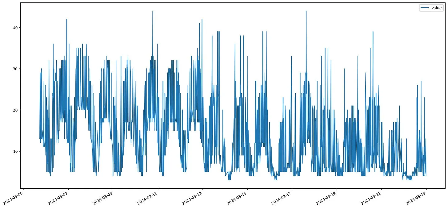
The battery level is measured approximately every 15 minutes and it’s pretty noisy, but we can smooth it over multiple readings and get quite a decent plot. We can also add in markers for the start of each day and we can see a pretty interesting pattern.
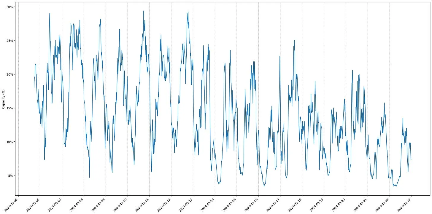
If we zoom into just a couple of days things become even more clear:
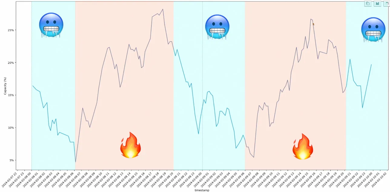
We keep our heating off overnight, and it turns off fairly early. This means that during the night the room with the switch in gets pretty cold. And as the room cools down the battery performs less well. Then around 6 or 7am, the heating comes back on and the battery starts to warm up. The battery performance goes up as it gets warmer!
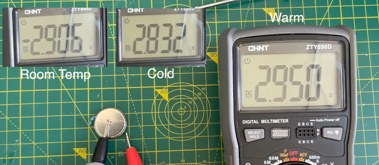
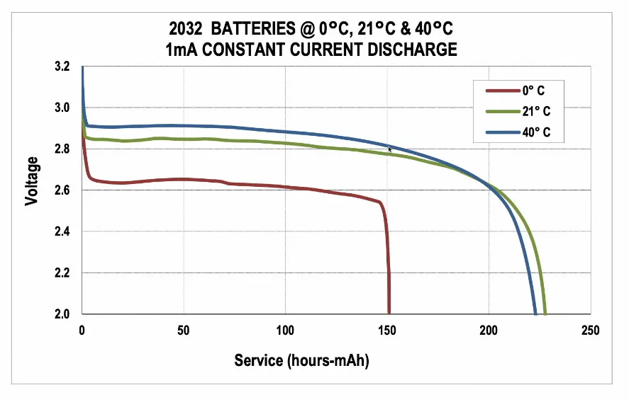
I did a few measurements of the battery at different temperatures, room temperature, after being in the fridge for a while, and then after being warmed to body temperature. It’s quite a dramatic difference in performance.
This is what we would expect, but it’s nice to get our own confirmation of the fact :)
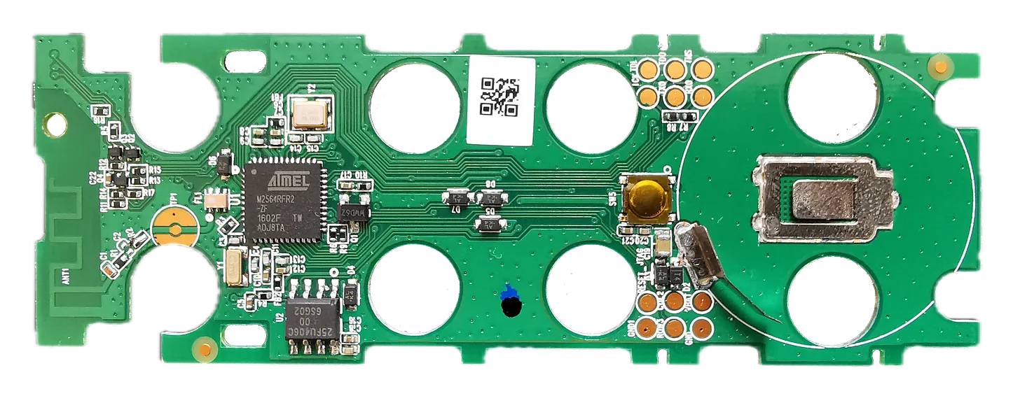
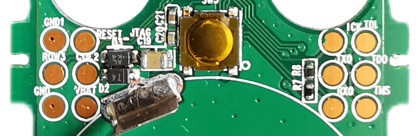
For the replacement battery I was thinking of using a rechargeable lithium coin cell. But there is a slight problem, looking at the PCB and buzzing out some of the connections I can see that the power pin for the main IC - an ATmega256RFR2 is directly connected to the coin cell.
Interestingly the ATmega256RFR2 does have a built in voltage regulator - but unfortunately the maximum allowed voltage is 3.6V. A fully charged lithium coin cell will have 4.2V, so it could damage the CPU. So we’ll need to stick with disposable cells for now…
The PCB is pretty simple, on the left we have the PCB antenna along with its matching network of passive components. The large IC is the MCU, the smaller IC below the MCU is a flash chip, and the 3 pin IC to the right of the MCU is a MOSFET. This MOSFET is used to control power to the flash chip, so the MCU can power down the flash when it is not required.
There are some interesting test points that may merit further investigation at some point - but that will be for a future project…
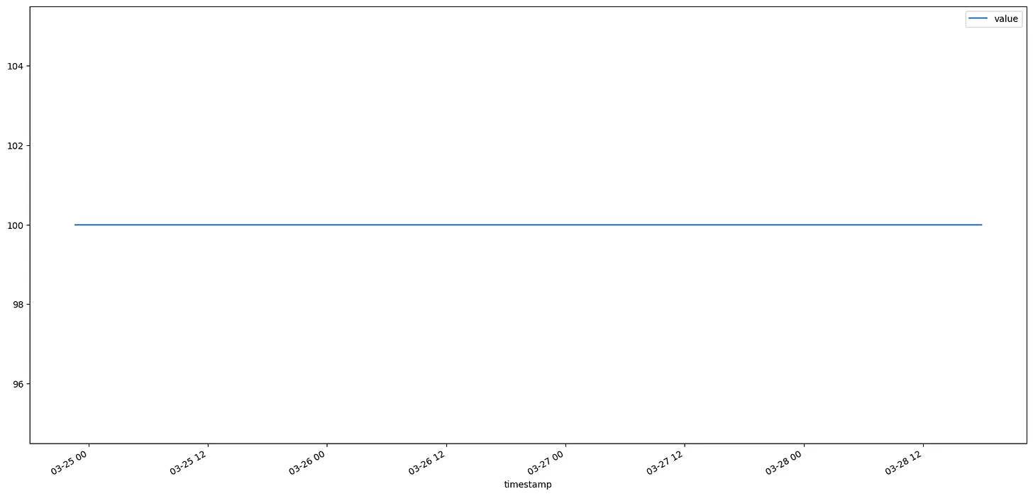
With a new normal non-rechargeable coin cell installed we get possibly one of the most boring charts in the world. We’re going to get 100% reported until our battery drops below 3v. Which might take some time. But I’ll keep an eye on it and will post if anything exciting happens!
Have a watch of the video - it’s got a lot more detail in it: