I’ve got a bunch of Philip’s Hue Color light bulbs, so I thought it might be fun to take one apart and do a bit of hacking.
If you’re here from Hacker News - watch the video - it’s really good! (Even if I do say so myself)
Disassembling the Hue Light Bulb
First, we need to open up the light bulb. Using a spudger, carefully pry the plastic diffuser away from the base, working around the stubborn silicon sealant. I got slightly bored and once I’d made a gap shoved a screwdriver in there to pry it off.
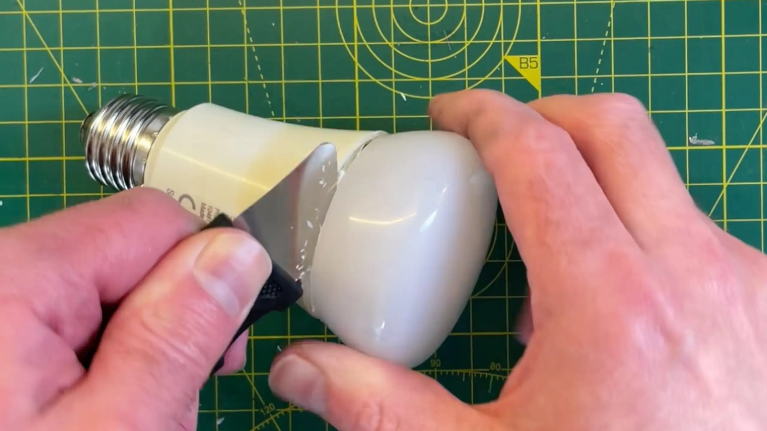
Next, remove the inner diffuser and the aluminum PCB with the LEDs on it. You might need to remove some surrounding plastic and metal for this.
To pop off the base of the light bulb I squashed it in a vice until the plastic cracked - you may want to find a less destructive method.
Inside the Hue Light Bulb
The power board and the logic board are separate components, they separate quite easily even when covered in the potting compound. Once they are separate you can attack each on in turn. Removing the potting compound from the power board is pretty easy. For the logic board there’s a plastic surround and the potting compound can be pretty difficult to get off - it’s easy to lose or damage some of the small ICs.
But after a bit of work you’ll end up with these three PCBS:
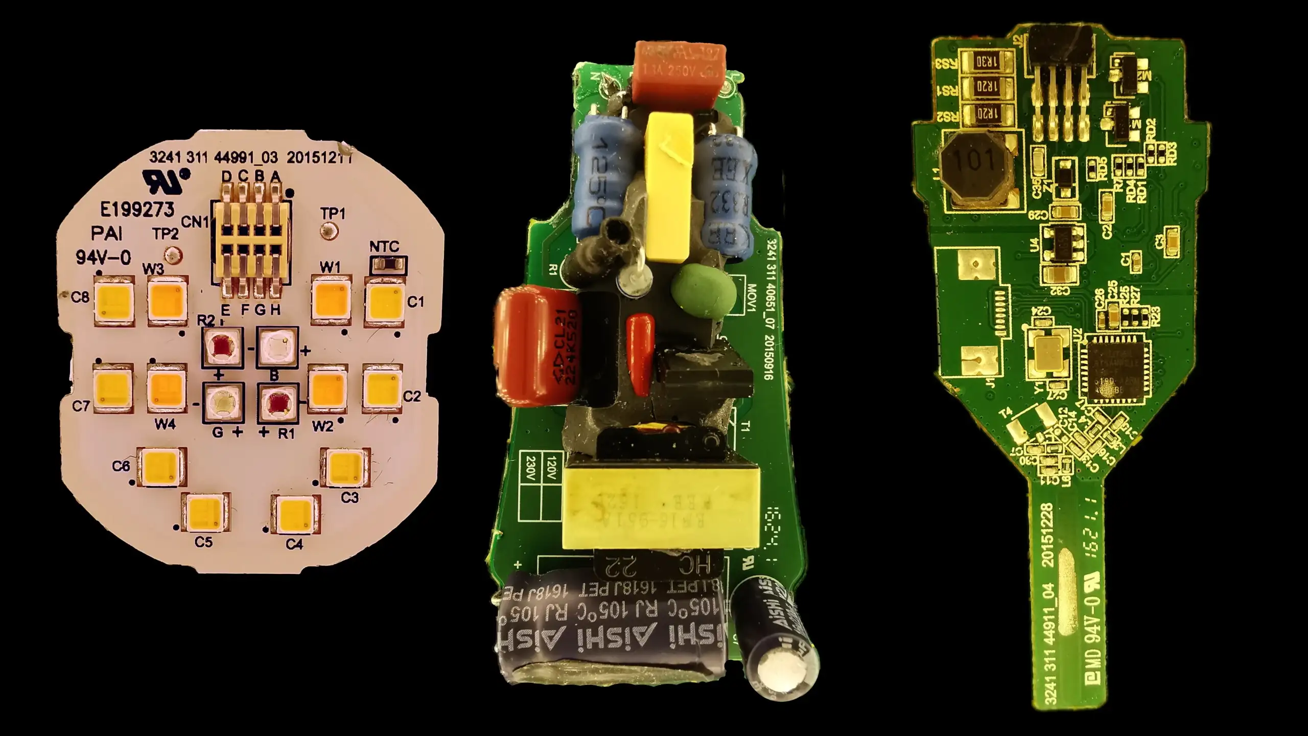
The Power Board
There’s nothing too exciting about this - it takes in the mains voltage, runs it through a bridge rectifier and then there’s a switch mode power supply generating 5V along with a hight voltage (probably around 24V) for driving the LEDs.
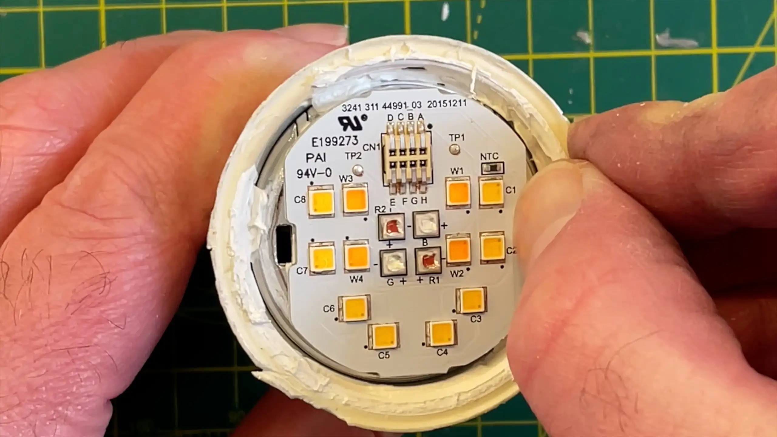
LED PCB
The LED PCB has an 8-pin socket labeled A to H. B and C were pretty straightforward - they just connect to the thermistor. The other pins were slightly confusing, but by connecting the power supply through a resistor and trying different combinations, we can determine which pins that control the various LED colors.
This gives us the slightly confusing schematic below - but don’t worry all will become clear:
The Logic Board
The logic board has 5 P-Channel MOSFETs, buzzing out the source and drain of these we end up with this much more sensible schematic.
Each set of LEDs can be bypassed by turning on the MOSFETs - it’s pretty clever.
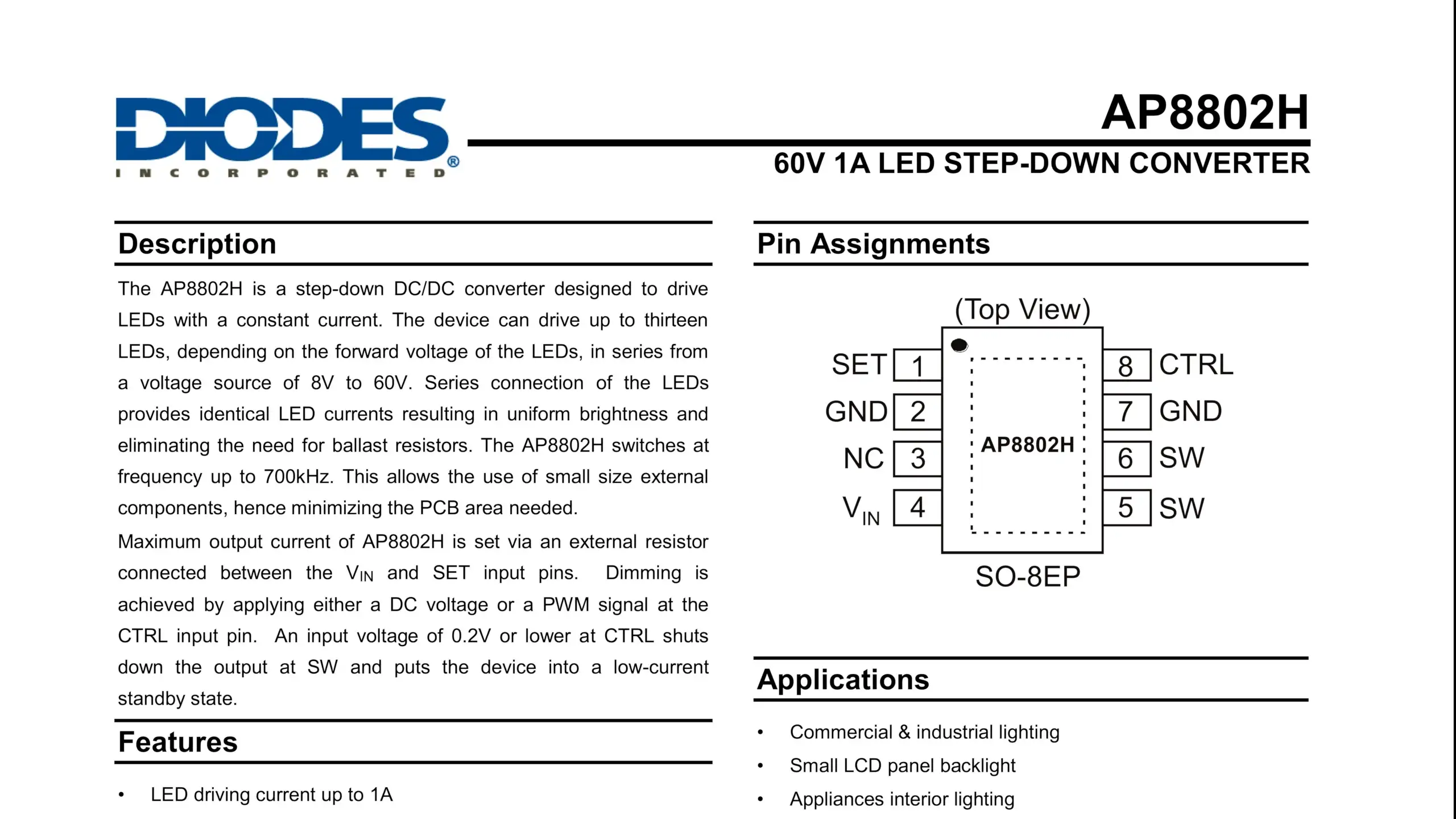
The board uses an AP8802 step-down constant current LED driver, capable of supplying up to 1A. It’s configured to supply around 0.5A to the LEDs. What’s very clever with the way the LEDs and MOSFETs are laid out is that we only need one LED driver chip for all the LEDs - this is a relatively expensive component compared to the jelly bean MOSFETs, transistors and other components.
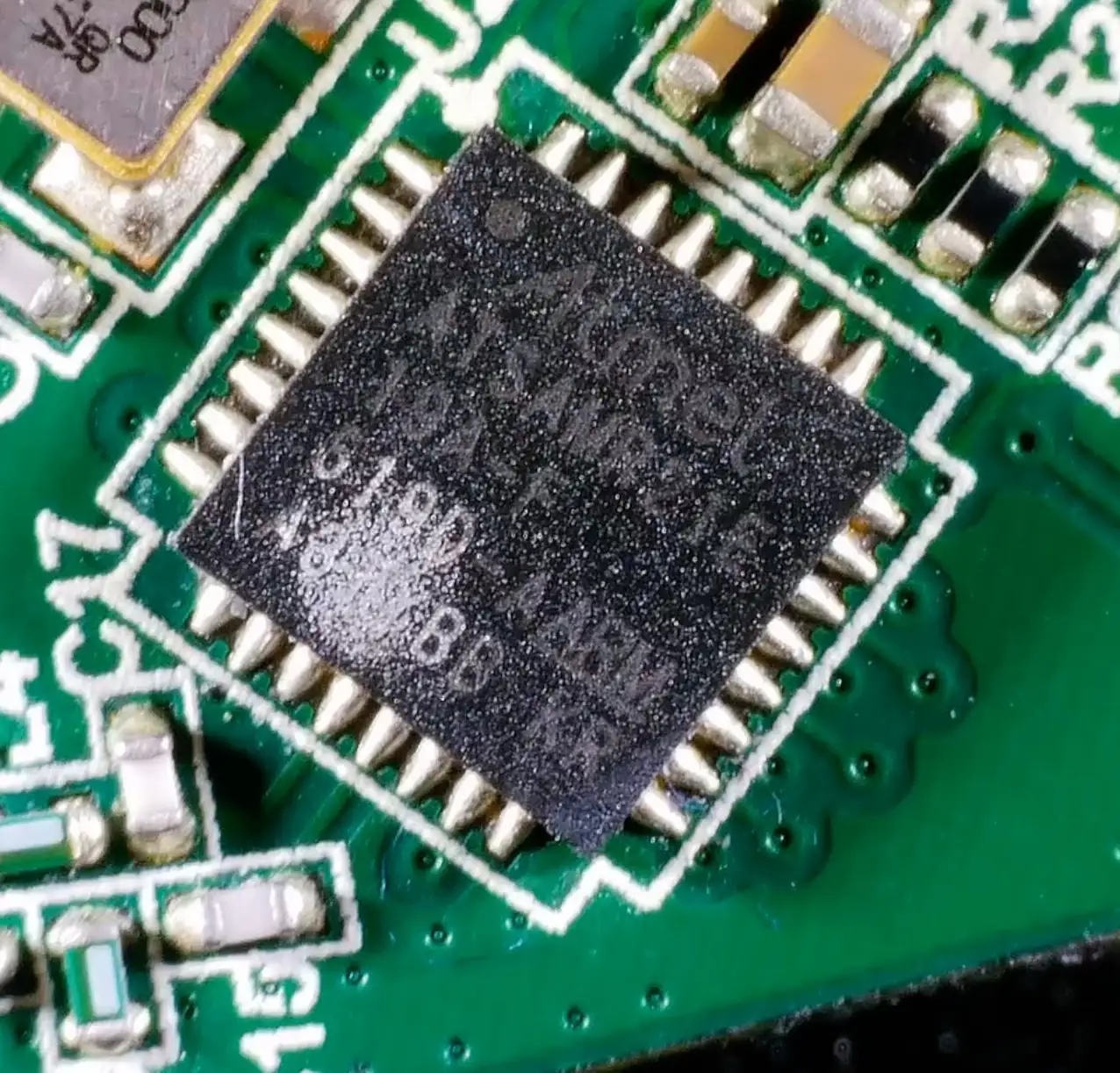
The MCU on the logic board is an Atmel SAM R21, a 32-bit ARM Cortex M0+ processor with a 2.4GHz ISM band transceiver for Zigbee communication. It has 256KB of Flash and 32KB of SRAM and runs at 48MHz.
The transmitter on this uses a PCB antenna with a bunch of capacitors and inductors to tune it to the right frequency.
Does it still work? And some more reverse engineering
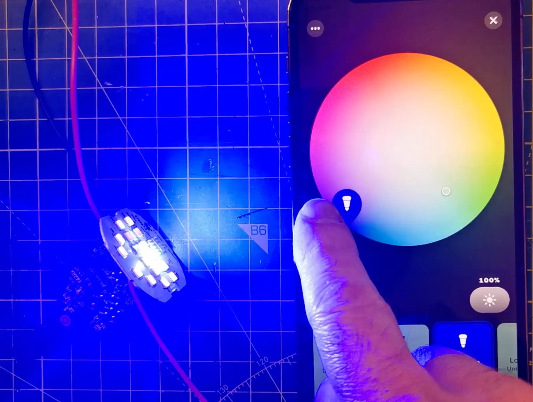
It does! If we solder some power cables on and provide it with 5V the light bulb shows up in the Hue app on my phone. It we connect 24V to the LED supply then they light up. We can control the colors from the Hue app - though since I lost one of the ICs we don’t get perfect colors.
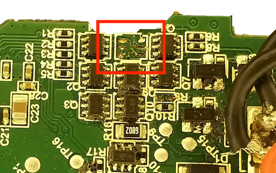
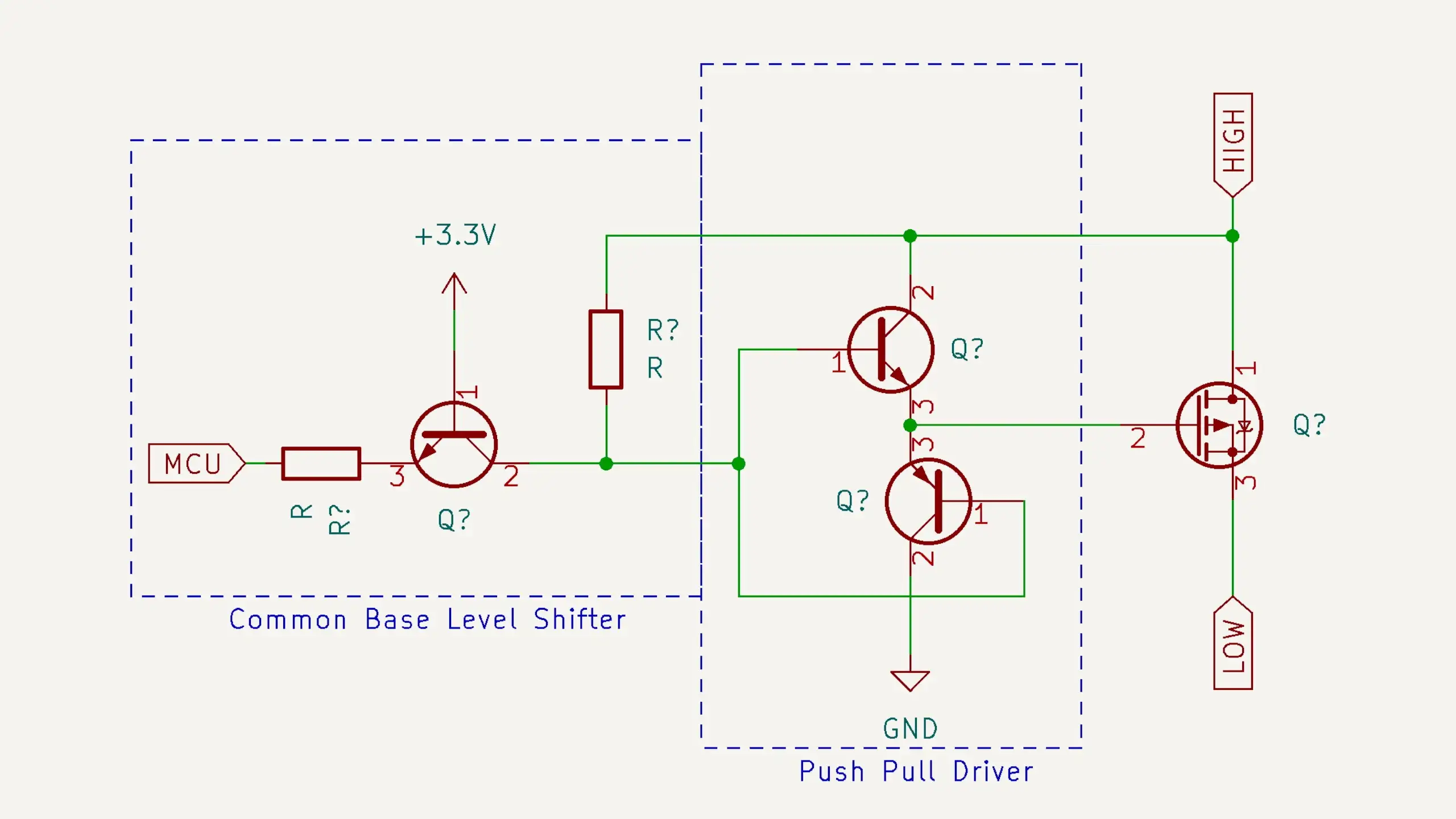
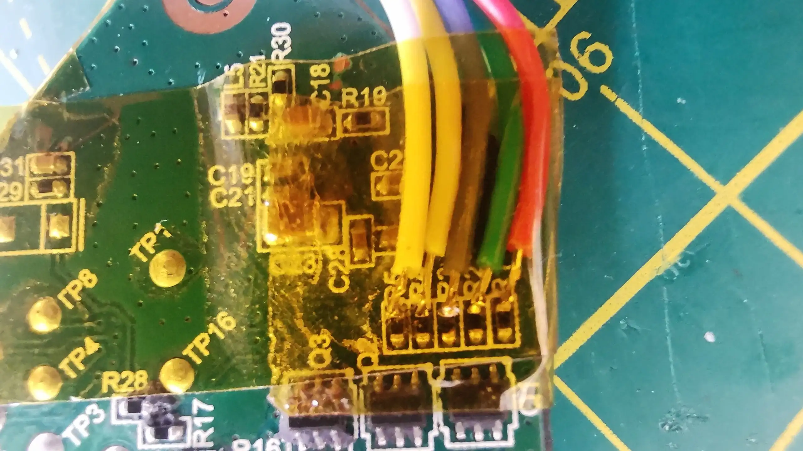
With the board we can work out what signals are coming from the MCU. These resistors here are connected directly to the MCU and go through this set of ICs to drive the PMOS FETs. The schematic is something like this - we have a level shifter followed by a push-pull driver connected to the gate of the MOSFET.
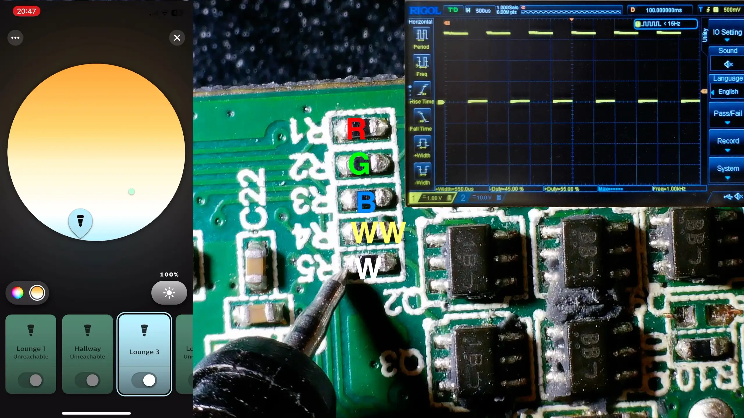
Probing the resistors while changing the color in the Hue app we work out the signals for each of the colors and for the white LEDs.
The last thing I checked was the control input of the AP8802 - I wasn’t sure if this was being used to control the overall brightnesss, but it turns out that this is just left floating and is only pulled low when the light is fully turned off.
Hijacking the signals
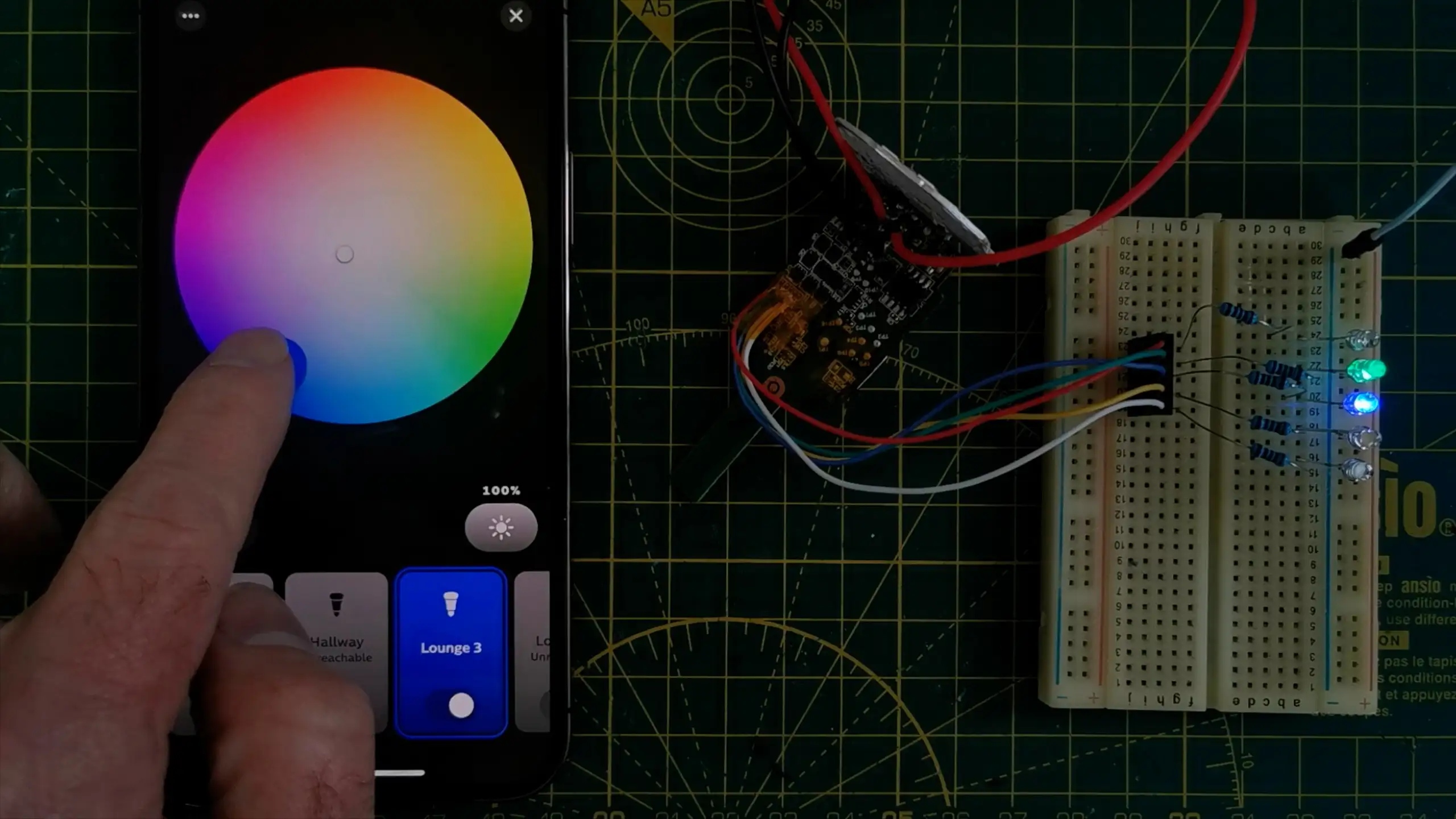
With the R,G,B and white signals worked out we can now solder some wires to the MCU side of the resistors and connect them to a breadboard. By driving LEDs at low power directly from the MCU we can create various colors and control the brightness.
That works pretty well, we can control the LEDs without any problems. All three colors work and the two whites also work - though I’m suspicious that the “warm white” LEDs may be used for yellow.
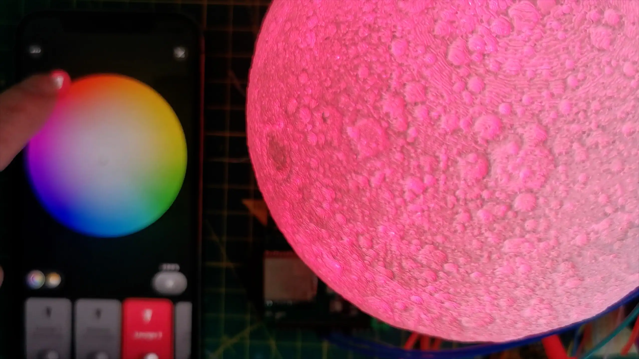
I also tried out my old Moonlamp - it’s the first electronics project I posted to YouTube.
It’s got a RGB LED with a common annode. Since it doesn’t have a white LED I’ve just ORed the signal in with the RGB signals.
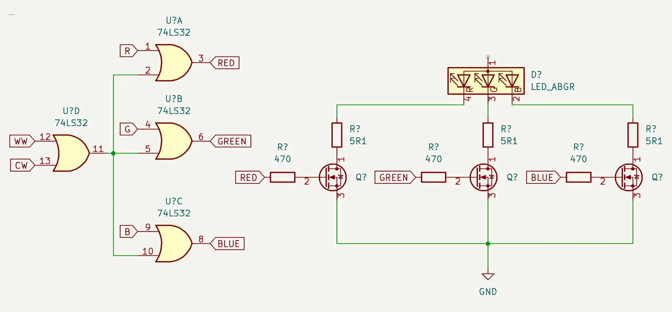
I’ve used my old board which already has MOSFETs on it for driving the LEDs. It works really well!
If you want to watch a video of it in action you can see it here: