This is a fun little battery-powered train set…

You can buy your own one here.
But out of the box it has two “features”:
- It’s unbelievably loud (the kind of loud you don’t want in your living room for more than 30 seconds)
- It eats four AA batteries living in the coal car
You can listen to the noise in all its glory at the start of this video:
So this was an excuse for a bit of train surgery: make it rechargeable, and give it a proper volume control.
What we’re starting with
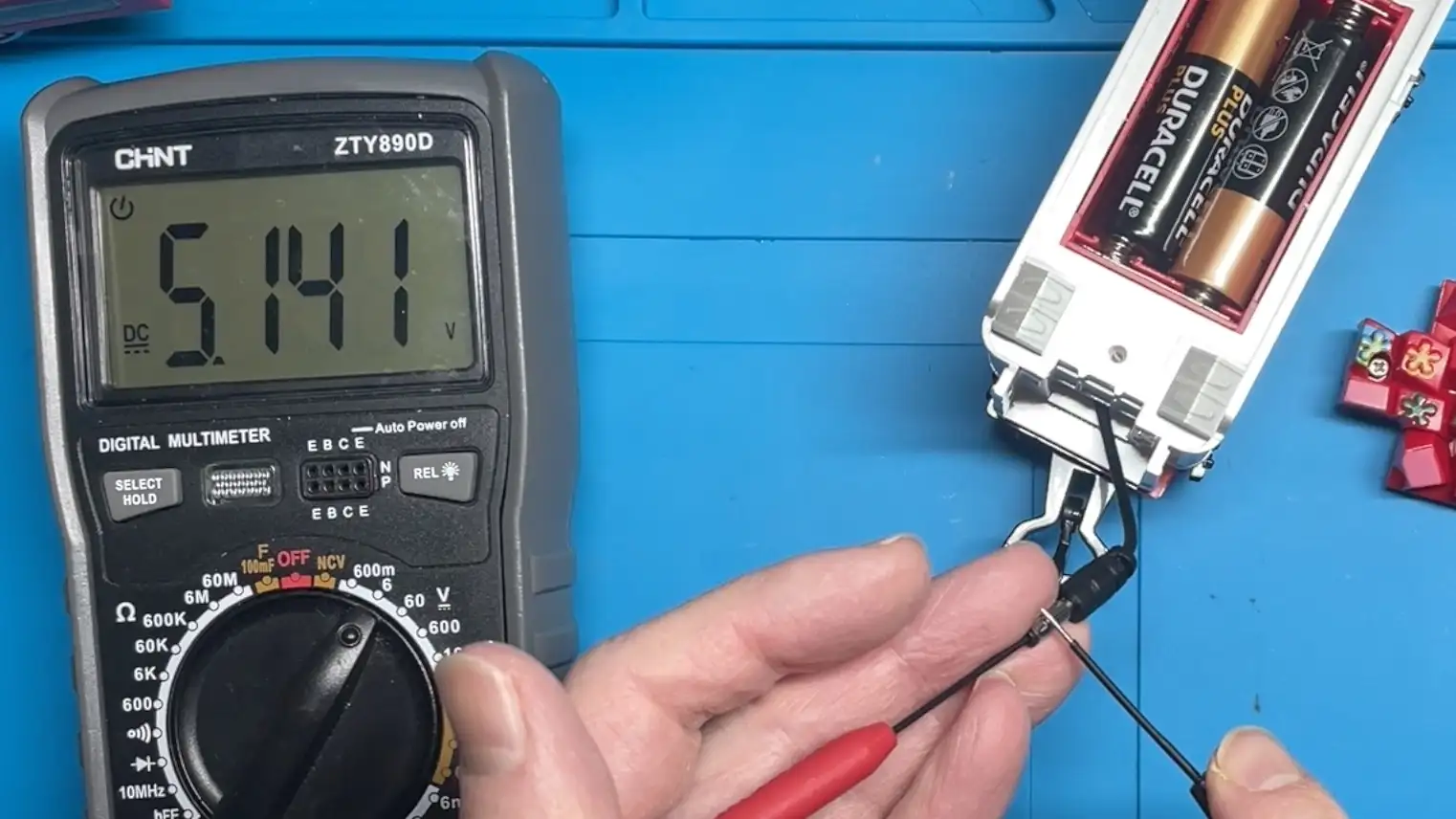
The power pack lives in the coal car and holds 4×AA. Before changing anything, I wanted to know what voltage the train actually expects.
With the existing batteries already a bit tired, the output measured about 5.1 V. With fresh alkalines you’d expect something closer to ~6 V.
Quick teardown (and where to tap in)
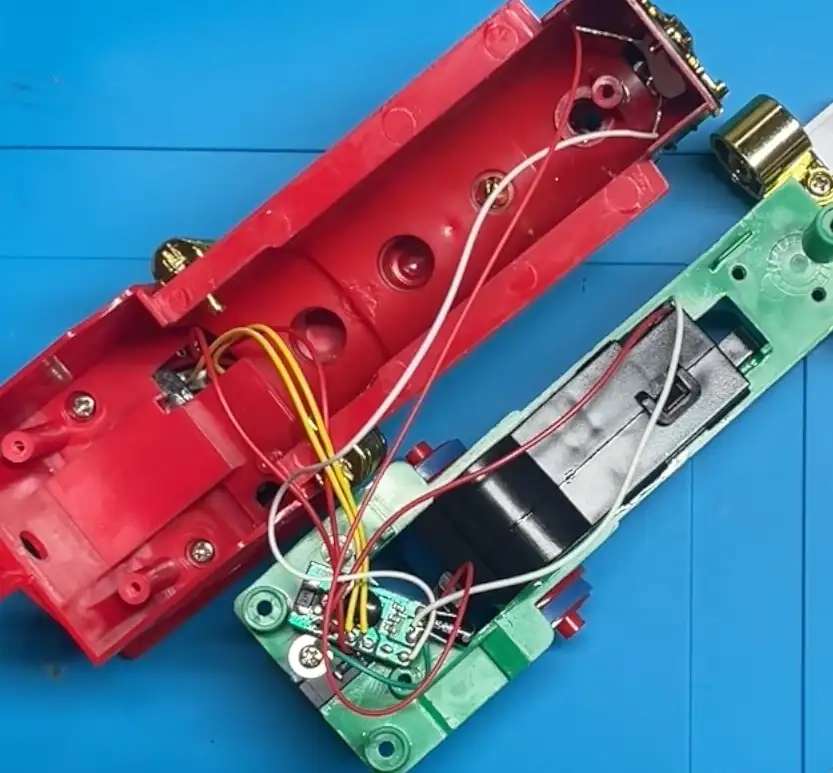
Opening the locomotive was pretty straightforward - we have the legendary visible screws.
Inside the engine is a small PCB with the usual blob IC, plus a whole bunch of wires:
- Two wires to the speaker
- Wires to the power switch
- Two wires to the motor
- Two wires to the front LED
Parts used
This is very much a “what’s in the parts drawer?” mod. The final setup was:
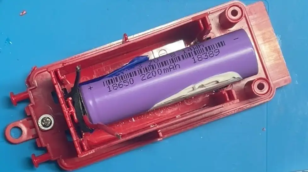
- 18650 Li‑ion cell (single cell, 3.7 V nominal, 2200mAh)
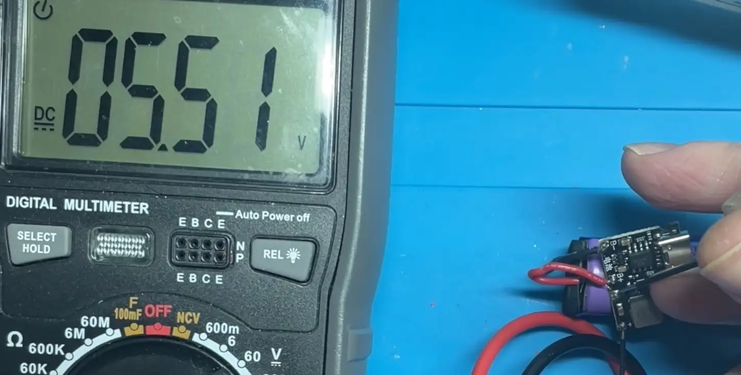
- A combined charger + protection + boost module (with an adjustable output voltage)
- A potentiometer used as a simple volume control in series with the speaker
- Wire, solder, and a quantity of hot glue that we’ll call “structural”
Making it rechargeable
The plan was simple:
- Put the 18650 cell in the coal car
- Boost it up to roughly “4×AA voltage”
- Feed the train through the existing power connector
Fitting it was the main challenge. The coal car has an internal red plastic compartment that needed to be… re-engineered… to make room for the cell.
Once there was space, the wiring was straightforward:
- Battery → charge/protect/boost module input
- Module output adjusted to around ~5.5 V
- Module output → connected to the plug coming out of the coal cart
I set the output to around 5.5 V — nicely in the middle between “fresh AAs” and “nearly flat AAs”.
One surprisingly nice thing is they did include a PTC fuse inline with the batteries - a nice soft start/safety feature.
Before plugging anything in, I did a quick polarity sanity check because toy wiring colour conventions are often a work of fiction. In this case the connector was centre positive.
With the speaker temporarily disconnected (to preserve my hearing), I plugged it in and… the wheels on the train went round and round. Success!
Adding a volume knob
Next problem: the speaker. The easy way to make something quieter is to disconnect it, but a volume control is much nicer.
The simplest approach here is to put a potentiometer in series with one speaker lead, using it as a variable resistor. With the pot turned up you get full volume; turned down it becomes civilised.
This worked immediately on the bench: at minimum it’s almost silent (you mainly hear the motor), and at maximum it’s back to the original “wow that’s a lot”.
The mechanical hack (aka: “please don’t judge my glue”)
An internal pot is only useful if you can actually reach it. I wanted the knob accessible from the outside.
So I:
- Chopped the top off an existing plastic piece to use as a knob cap
- Stuck the top I chopped off onto the top of the potentiometer
- Glued it all together
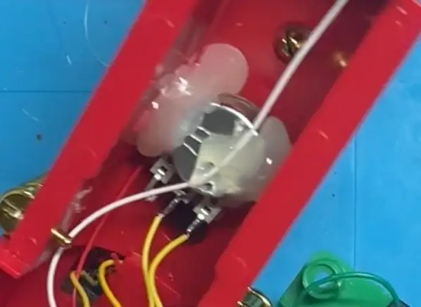
In the end a combination of a lot of hot glue along with superglue and patience made it all work.
I did spend a lot of time with my fingers stuck together…
In the end it’s slightly wonky, but it works, it’s solid, and a bit of gold paint hides the terrible workmanship.
Result (and one remaining annoyance)
The end result is exactly what I wanted:
- Rechargeable power (no more burning through AAs)
- Adjustable volume (from “barely there” to “festival headliner”)
The only thing I didn’t solve is the drivetrain noise: it uses plastic gears and the mechanical clatter is now the loudest thing at low volume.
Watch the full build
If you want to see the teardown, the battery conversion, and the volume knob bodging in real time, the full video is here: