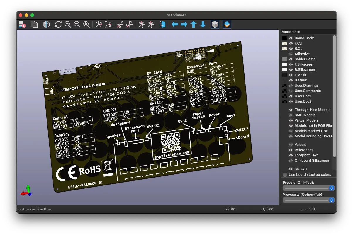
If you’re following along with the ESP32 Rainbow project, then you’ll have seen that we’ve added some pretty nice silk screen to the back of the board.
Now, you can obviously use the tools built into the PCB tool in KiCad to design your silk screen, but it’s pretty limited - it’s not a graphic design tool. But it is surprisingly easy to import graphics into KiCad. This opens up a whole world of custom silk screen designs.
You can see my process in this video:
It is pretty simple to do. There are some things that it’s worth being aware of.
KiCad will let you import images using the Image Converter tool.
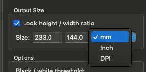
There’s a couple of things to bear in mind. KiCad will work out what “size” the image is based on the DPI (Dots Per Inch) that is embedded in the image file.
So, imagine you have an image that is 300x150 pixels in size and is 300dpi. The physical size of that image will be 1inch x 0.5inch.
Fortunately, you can override all of this in the Image Converter tool, but it’s quite helpful if you’re creating an image from scratch to just set it up how you want it.
The other thing to bear in mind is that Silk Screen can only be black or white in KiCad - there’s no color and there are no shades of grey.
This can lead to some interesting effects if your graphics tool outputs anti-aliased output.

This can have some interesting effects when you come to threshold the image into black and white pixels. Here we’ve got the slider quite far to the left, our lines and text are quite thin.

But if we move the slider over to the right, everything gets thicker:
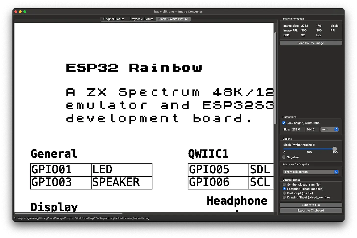
I prefer to get an exact WYSIWIG experience. So I’ve turned off anti-aliasing in my graphics tool. This removes any of the grey pixels and means that we’ll get exactly the same results in the Image Converter tool no matter where the slider is.

With our image imported, we just need to get the results out from the Image Converter. I prefer to just use the “Export to Clipboard” button.
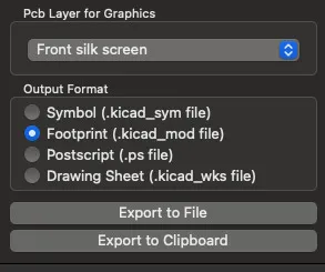
Once you’ve clicked this, you can simply open up the PCB and paste your design in. You can then position it and flip it to the back if needed.
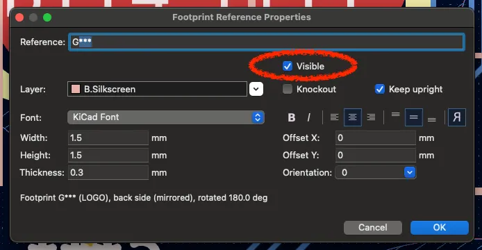
The only thing that you will need to remember to do is remove the “G***” reference text.
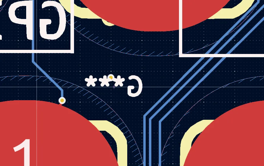
You can do this by double clicking on the text and then unselecting the “visible” checkbox.
And that’s it! I find the best way to preview the results is the 3D viewer. And it looks great!